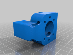


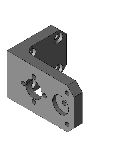
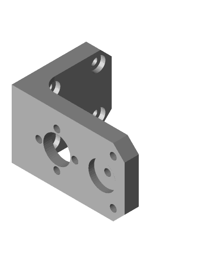
BLV 3 Point bed levelling
Model originally uploaded to Thingiverse at https://www.thingiverse.com/thing:4611244.
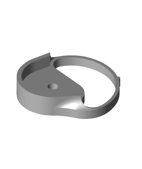
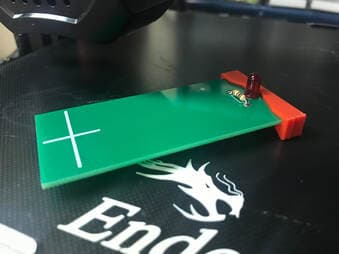
These are the bed mounts for my 3-point levelling system/kinematics for the BLV. These have been designed to work with the bed I designed, which can be found here: https://www.thingiverse.com/thing:3875857
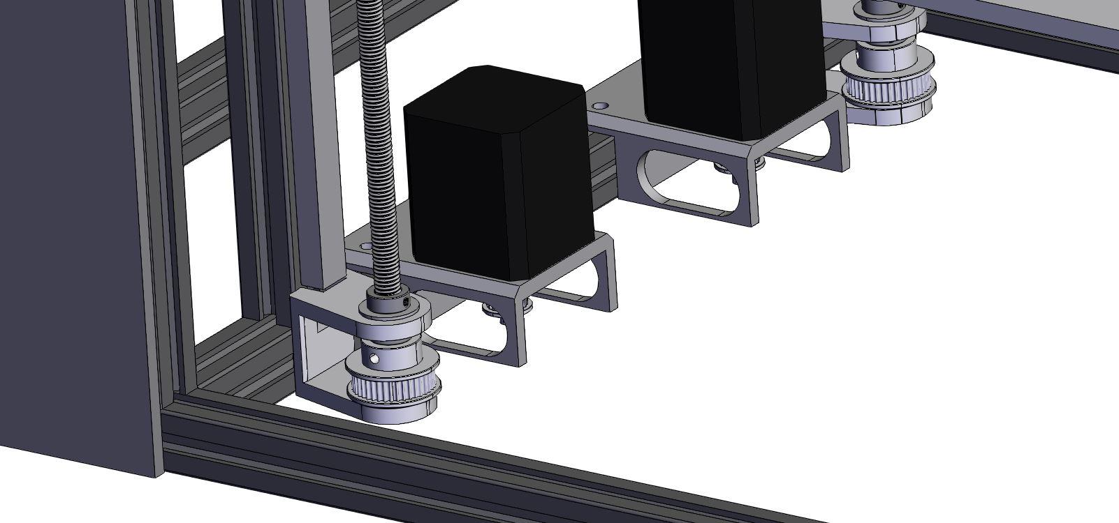
[UPDATE} Sometime ago I upgraded my printer to 1204 ballscrews, I have now uploaded the parts necessary to use my 3-point kinematics system. Note, as my ballscrews were a little long, I have lowered the stepper mounting position and use some adjustable height feet to raise the frame high enough.
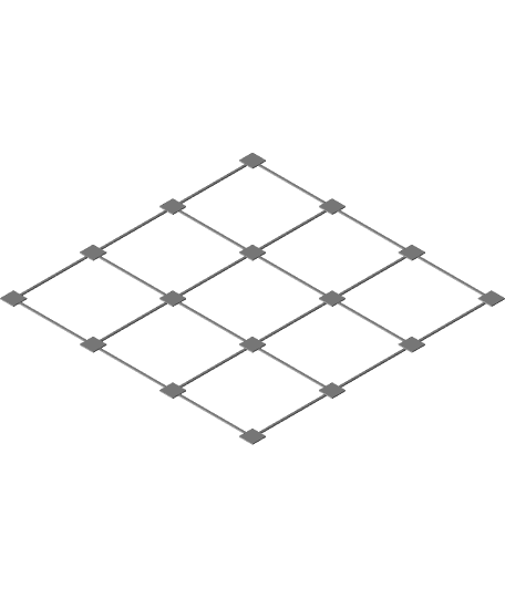
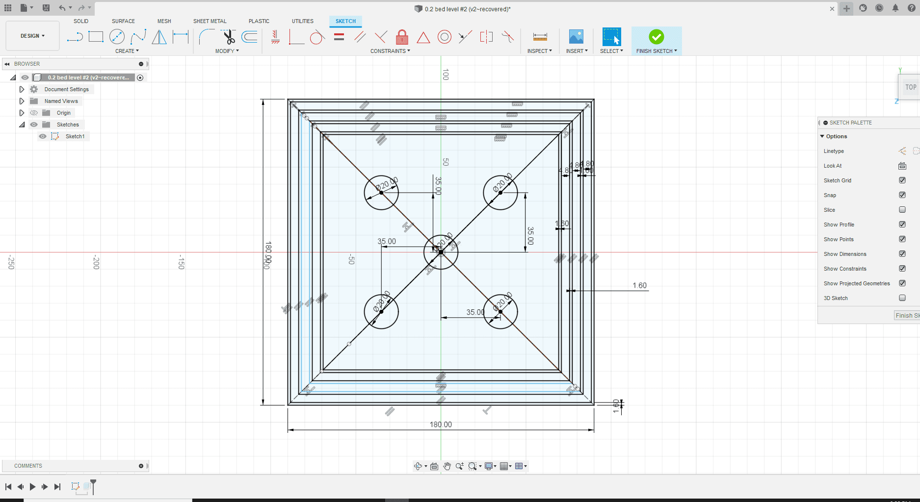
I have made a jig for easier placement of the aluminium extrusions that hold the rails. I have made this so on side with 1 z-screw, it is to be located 205mm from the front extrusion. Opposite side front extrusion for rail is to be placed 80mm from front extrusion (corner piece) and back rail extrusion is to be placed 230mm away from the front rail extrusion. Any questions, please feel to ask....I will try to provide answrs with diagrams but can't guarantee how quickly I will respond.
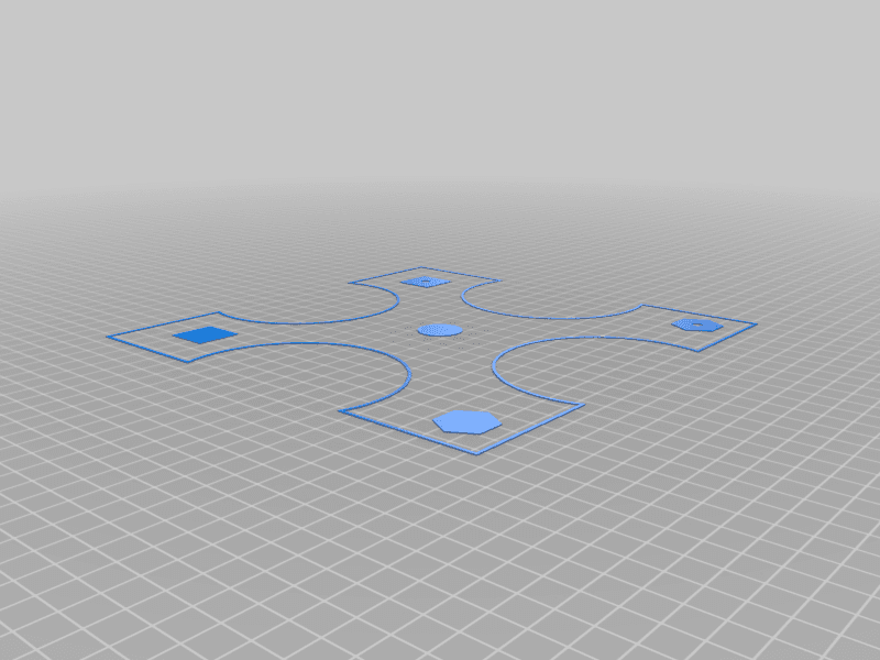
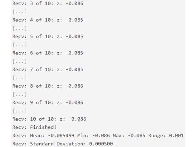
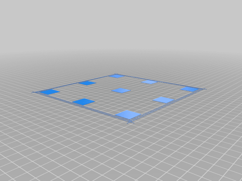
Add this line in your config.g for correct positioning: M671 X-15:365:365 Y175:50:300 S15 Please note, I have provided my bed.g file but I have set the the probe points with offsets for my probe, which will likely be different to yours. As such you will likely need to adjust the x and y positions for each of the three test probe locations accordingly (usually I'd recommend inline with the leadscrew on the Y-axis, and about 10mm in from edge of the bed on the X-axis.
Extra items needed (assuming you have a BLV MGN Cube and wish to change to 3-point levelling for the bed): 1x 2040 extrusion of length matching your existing two, 1x mgn12 linear rail matching length of existing two, 1x lead screw, matching length and pitch of existing two, 1x stepper motor matching your choice for the existing two, 1x nut for leadscrew, 4x M3 nylock nuts, 4x M3 x ~8mm to mount to mgn12 carriage, 4x M3 x 20mm screws to mount leadscrew nut, pack of 10 M3 x8 screws, similar amount of M3 t-nuts to mount the linear rail. 6x M5 x8 screws 6x M5 t-nuts For Balls (x3): Outer Diameter: Φ10 (mm) Thread: M4 Note: these are the same size as the Kosel K800 ball ends
1x magnet: bore size: 4mm outside diameter :12mm thickness: 4mm
1x magnet: 10mm diameter 2mm thick.
2x magnet: 15mm long x 6mm wide x 3mm deep For last mount, rectangular magnets used Note: must glue in:
...Possibly a duex2/5 if multiple extrusion also desired (for Duet2 Wifi/ethernet setups).
BLV 3 Point bed levelling
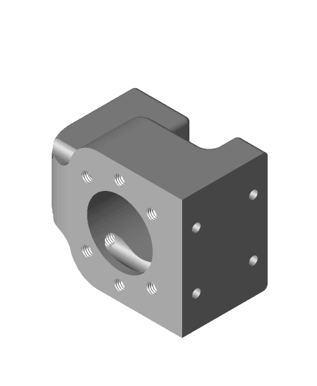
DLV 3-Point Kinematic Bed Mount
3-Point Bed Leveling Z-Axis Bed Mount.step
3-Point Bed Leveling Z-Axis Bed Mount.stl
Ender 3 Ultimate Bed Level

Ender 3 bed level test (dual extrusion) / offset calibration

kobra 3 bed leveling test

Ender 3 Bed Level Test
235 x 235 16 Point Bed Level Test
Ender 3 Pro Bed Leveling Knob with Nylon Nut
Bed leveling bushing for Ender 3 V2
Opto-mechanical Auto Bed Level Probe (Ender 3)
SolidCore CoreXY 200x300 with Stealth XY Mounts
Ultimate Ender 3 Max / Cr-10 Bed Leveling Knob Remix
Manual bed level for ender 3/ender 3 pro
CHEP E-Leveler Bed Level Tool End Cap
0.2 Bed Leveling
Ver4.0 Filament Friday Manual Bed Level for Ender Size Printers by CHEP
Perfect 1st layers! Ender 3 v2, Ender 3S1, Ender 3S1 Pro - 3x3 Calibration Bed Leveling Squares optimized for Professional firmware with UBL
bed leveling test