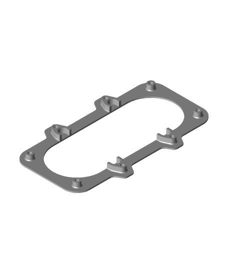
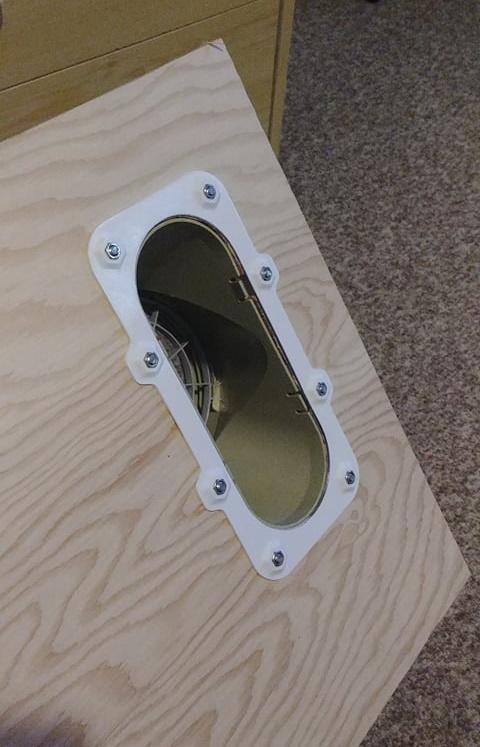
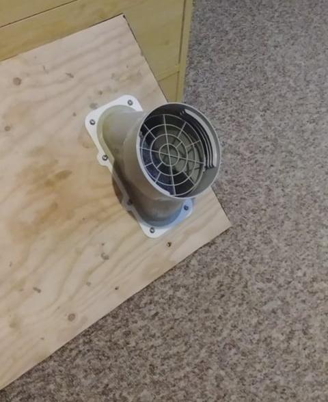
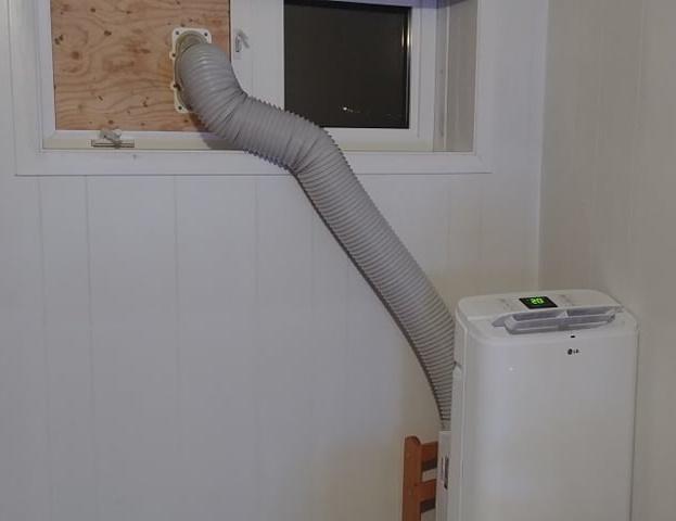
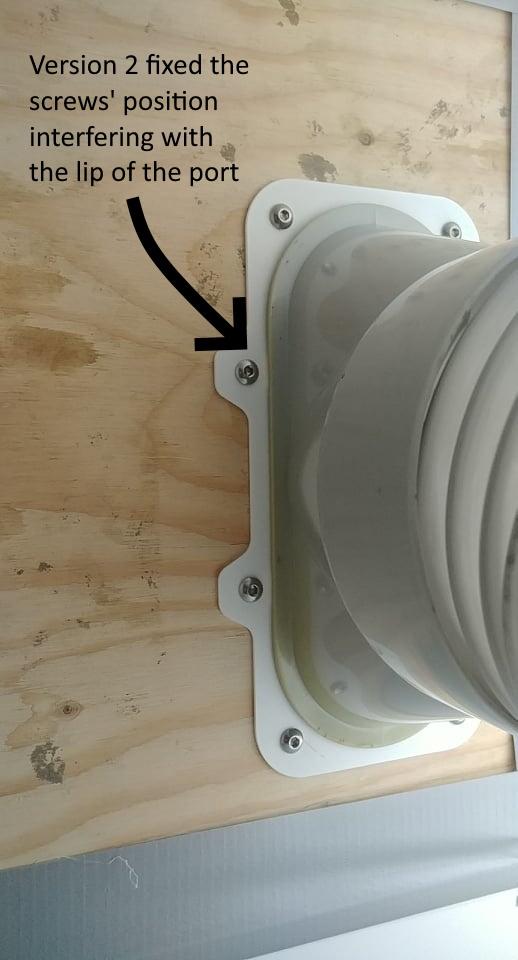
I couldn't install my LG air conditioning unit in any room of my new house because it was designed to be installed in a sliding window and my house only has pivoting windows.
I figured I could open the window and replace the window's bug screen with a veneer board and mount a bracket on it for the Air conditioner's exhaust port to attach to.
This thing uses these additional parts: - 8x M5 hexagonal nuts - 8x M5x16mm screws
The bracket pieces are 218mm long! The fit on my ender 3 was very tight and I had to remove any skirt and brim from my slicer settings for it to fit on the bed. the surface is rather wide, so they aren't really needed anyways.
** Brackets preparation ** Right after the print, I suggest using a drill or an Exacto knife to deburr and remove any extra filament residue. The screws should slide easily. It's not a problem if it's not done, but mounting the bracket will be harder.
** Prepare the veneer board ** I included a stencil in the project. Of course, you can eyeball it, but I liked using the sencil with my Dremel to have a more accurate cutout: - Draw every corner points in a rectangular pattern. the poins should be at the corners of a 190mm x 74mm rectangle. - Use a 10mm drill bit to make a hole on each corner - Sit the pegs of the stencil in the holes - Use your preferred tool to carve the middle hole (I used a drill to puch somes hole in the middle and a Dremel with a straight router bit for the perimeter.) - Check the fit of the "inner" part with your hole and make the necessary corrections.
** Assembling the part ** The part was designed to use M5 screws and nuts. I used 16mm long screws
I made an animation in fusion 360 showing how I did mount the brackets. it was more for the fun of it than actually thinking you guys would need a video... but this animation was more fun to make than I thought. Now it's made, so I might as well include it loll.
The video is down here. https://youtu.be/uU79Rl14tYo
How I Designed This I recently started trying to use Fusion 360 after a few years of amateur experience with Sketchup and truth be told, I'm rather proud of this design.
Here, you can see the build animation of the first version. after I printed it, I realized the middle screw were a bit too close to the border and were interfering with the exhaust port. it was functional, but I was confident I could also make the bracket stronger so I spaced the middle screws out of the middle hole and added a casing around the clips of the exhaust port.
The final result was very satisfying to me and now, I finally have AC in my home office.
here's the build animation for the first version : https://youtu.be/HX4udECkFOo
and the build animation for version 2 : https://youtu.be/cVpYTB1sKEc
