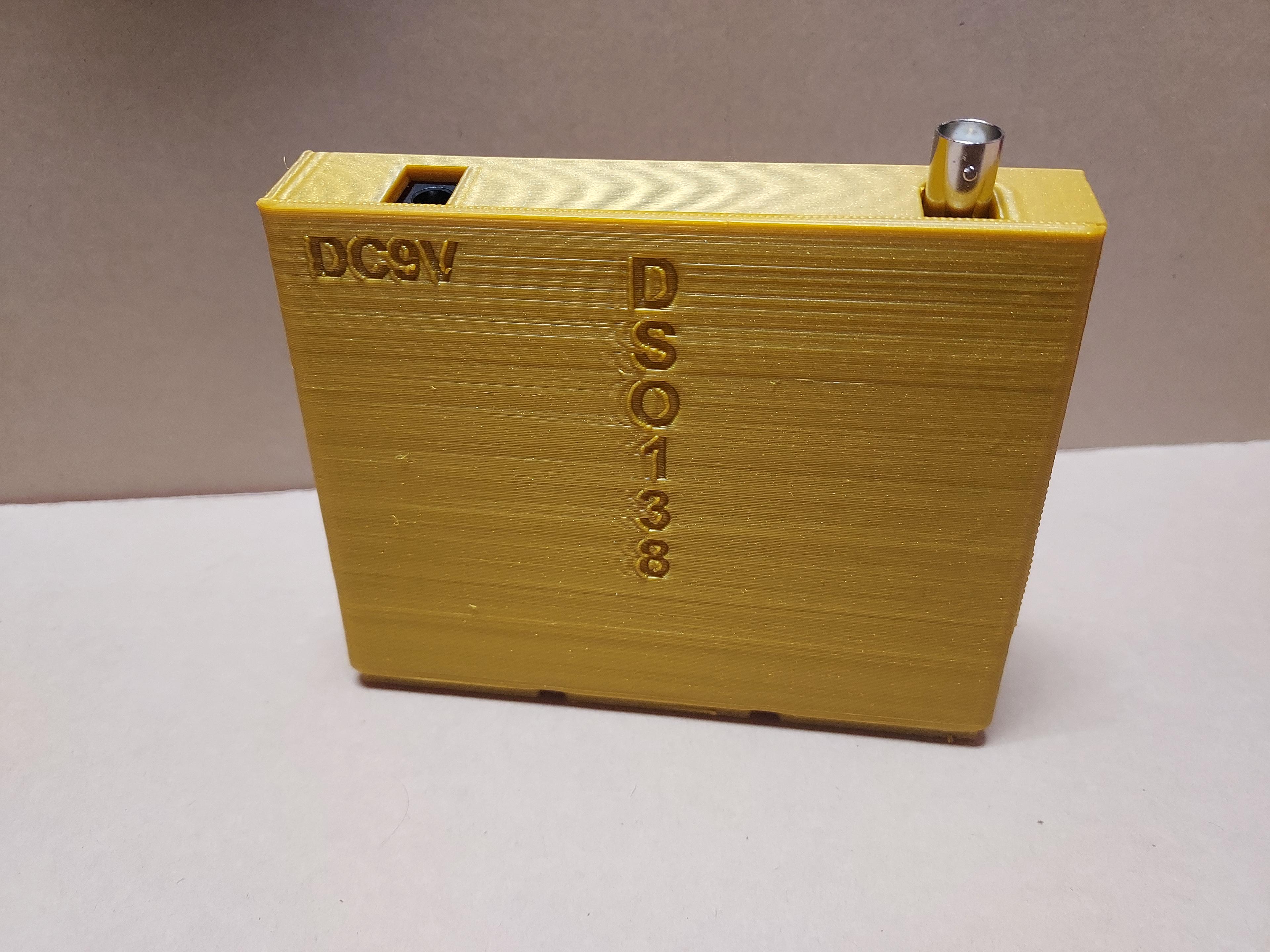
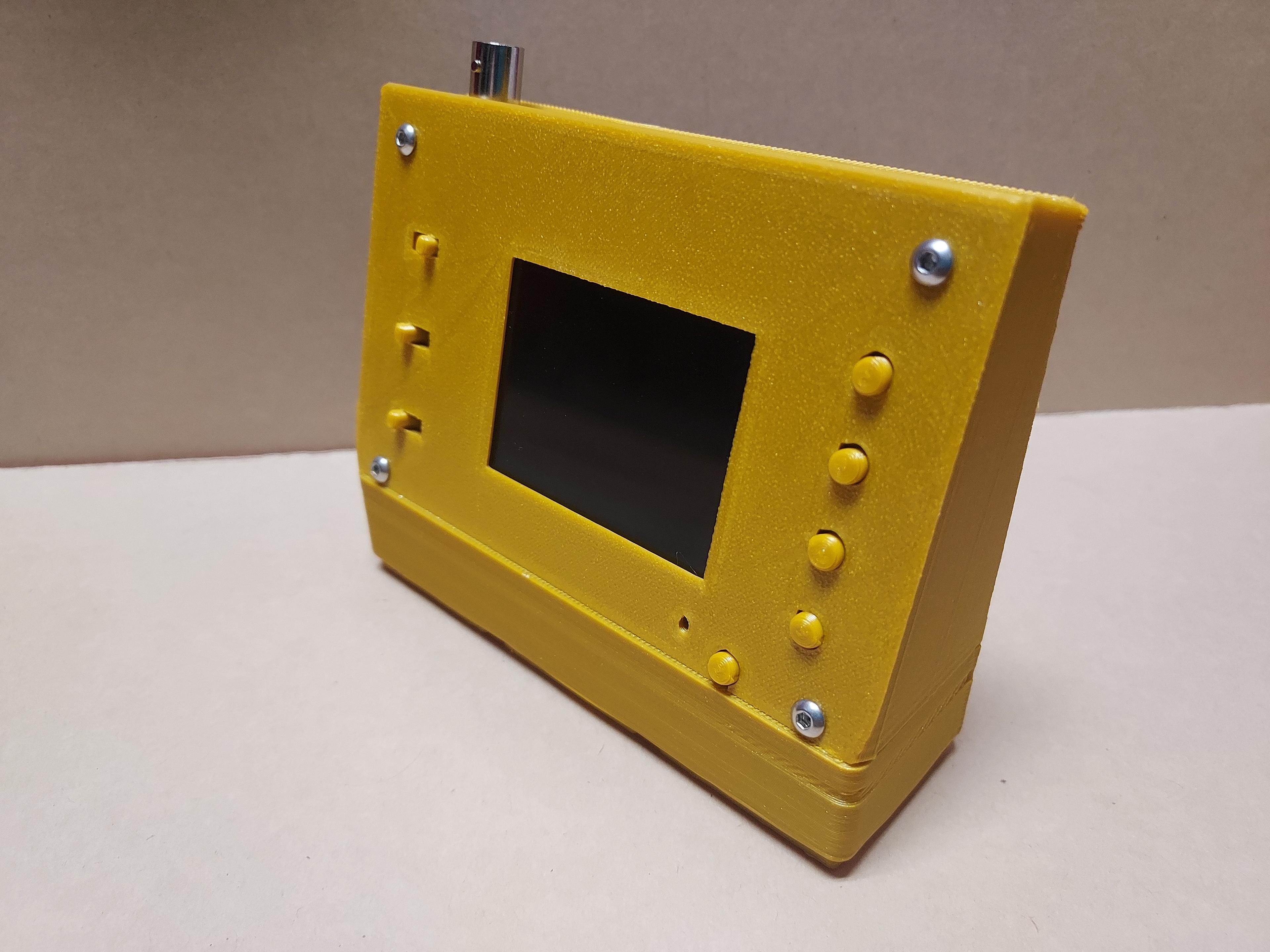
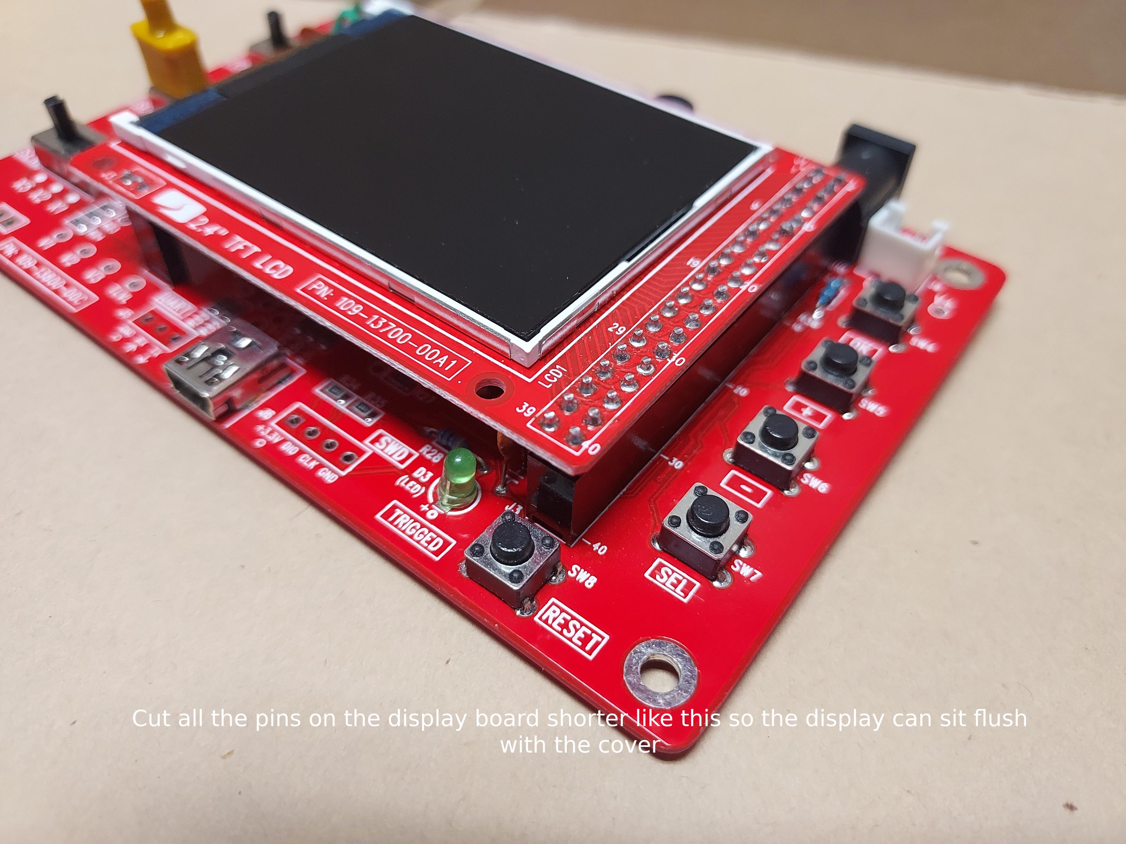
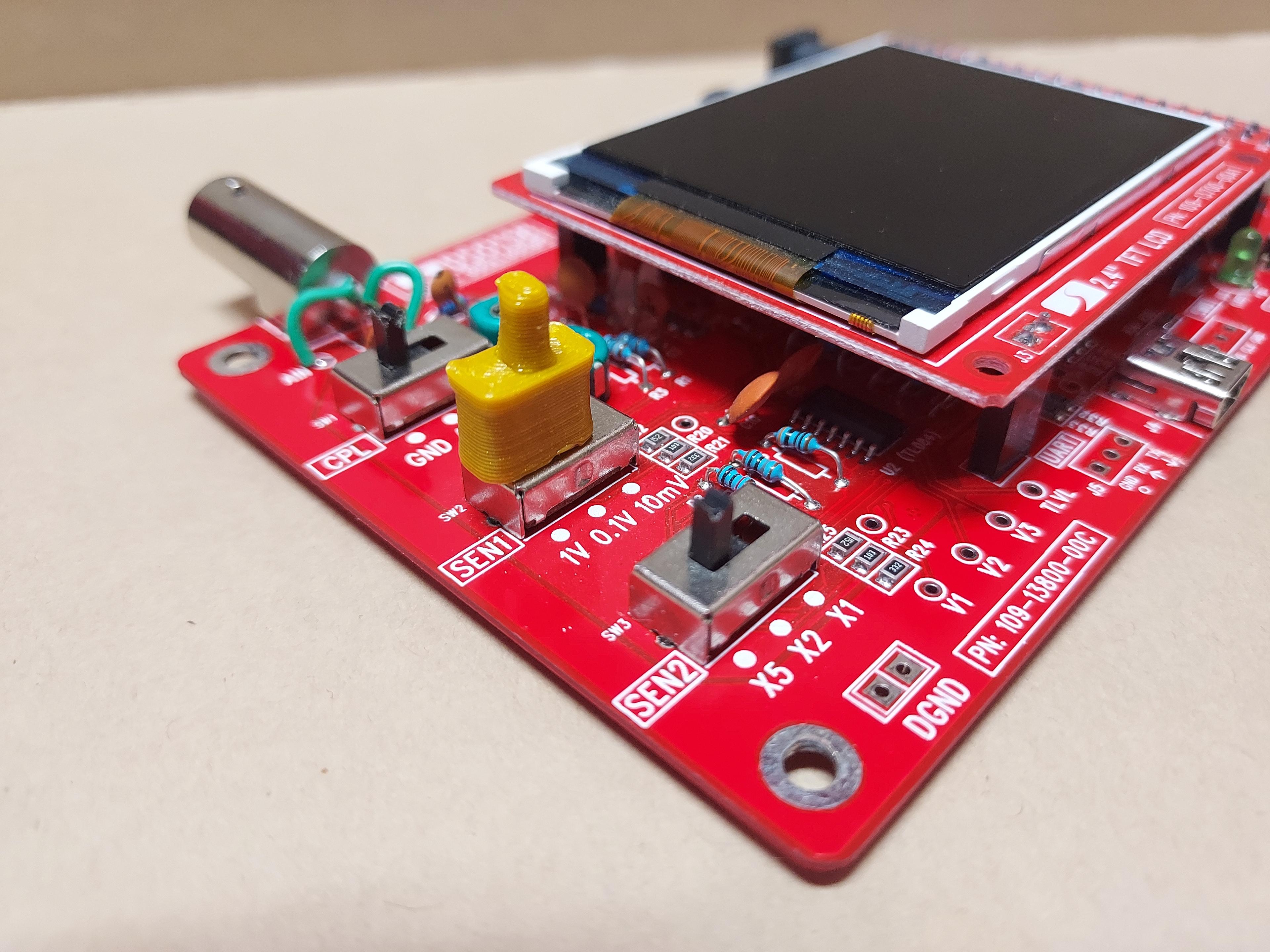
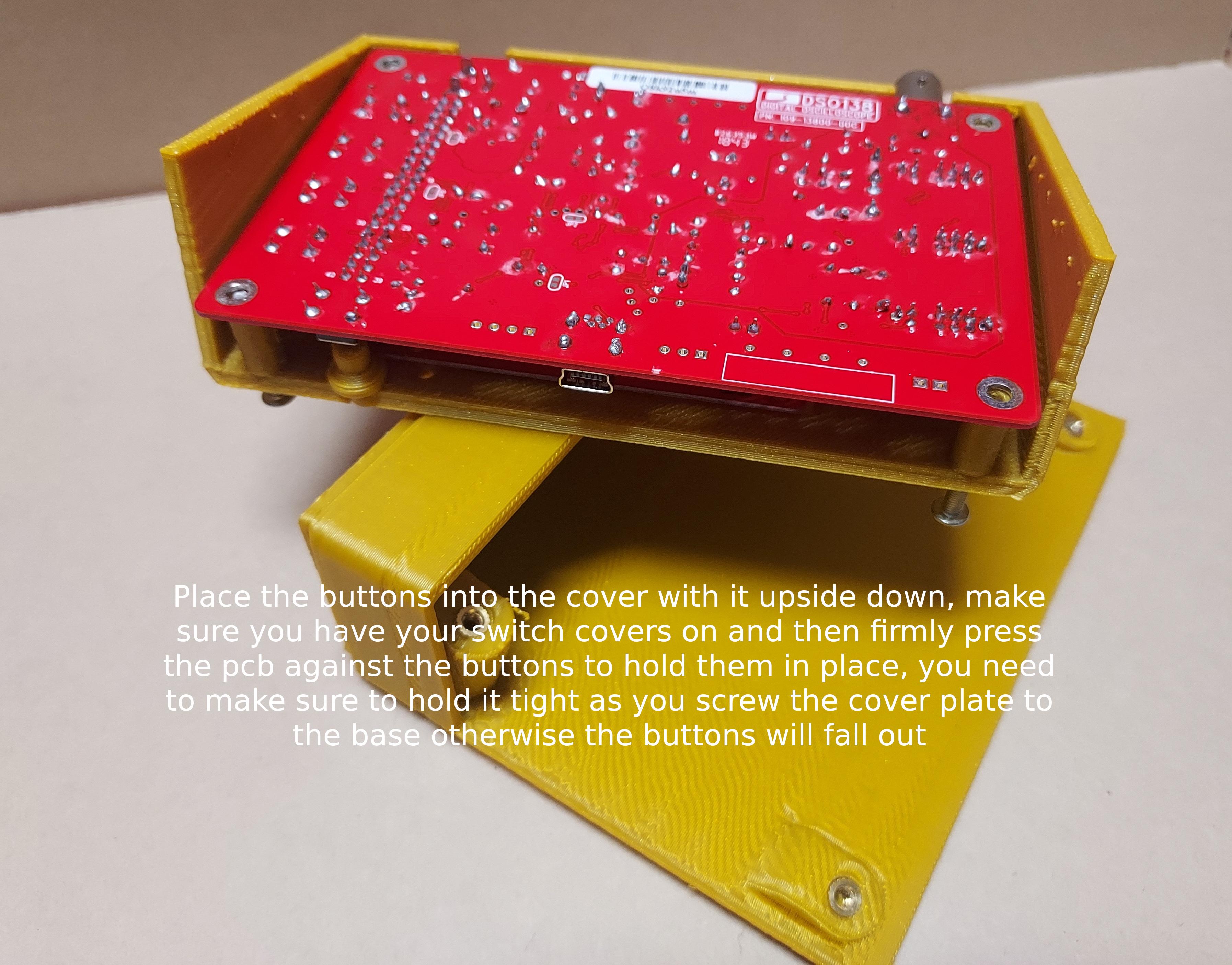
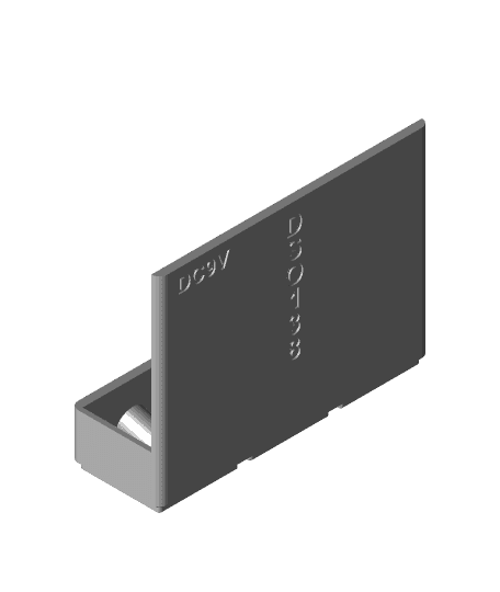
This is a 3x1 Gridfinity compatible enclosure for the DSO138 oscilloscope. It comes with two covers with one that has text and another without, the only three non 3d printed things this requires are the DSO138 itself, 4x M3x20mm bolts, and 4 M3x5mm diameter threaded inserts that are either 4 or 5mm long. You will need to use a soldering iron to press these 4 inserts into the holes on the base. You will also have to modify the screen pcb slightly by using a pair of nippers to cut the tips of all the pins on the upper display board so the display will sit flush with the cover. Then press on all three of the switch covers on the switches and make sure they are as flush with the switch housing as you can get them so they will not wobble on the switch stem. After that turn the cover upside down, put in all the button covers and press the main pcb against the cover and button covers tightly. Hold the pcb tight against the cover while you screw the cover into the base plate, if you hold it tight the button covers should not move. Once screwed together check all buttons and switches are working correctly. Happy printing!
