Model originally uploaded to Thingiverse at https://www.thingiverse.com/thing:3709082.
IntroductionThis little thingy is yet another supplement to the Smart Multi Filament Feeder project (SMuFF) as published here on Thingiverse but can also be used with other MMUs.
If you've watched my videos of the SMuFF, you might have spoted the "Filamess" in one of them.
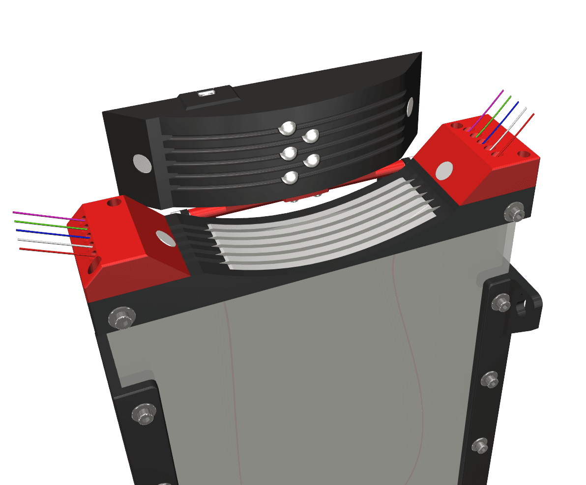
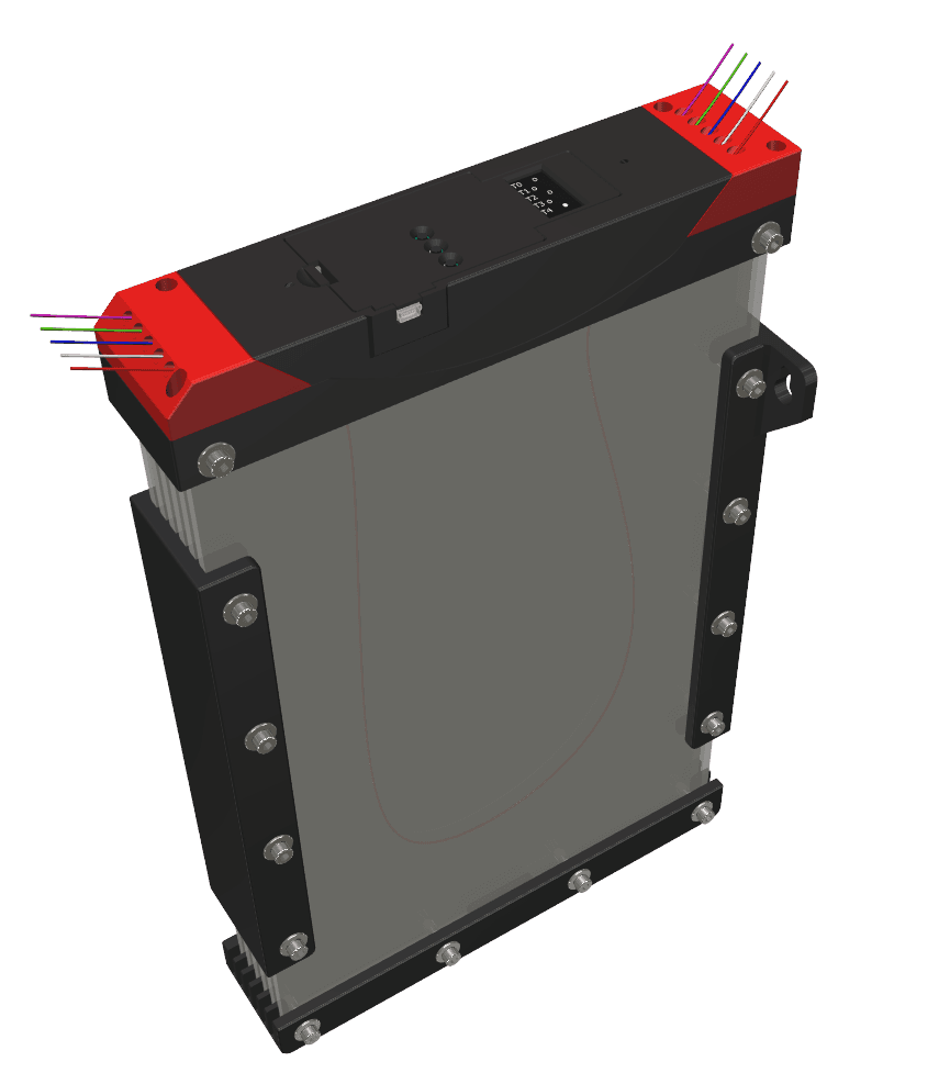
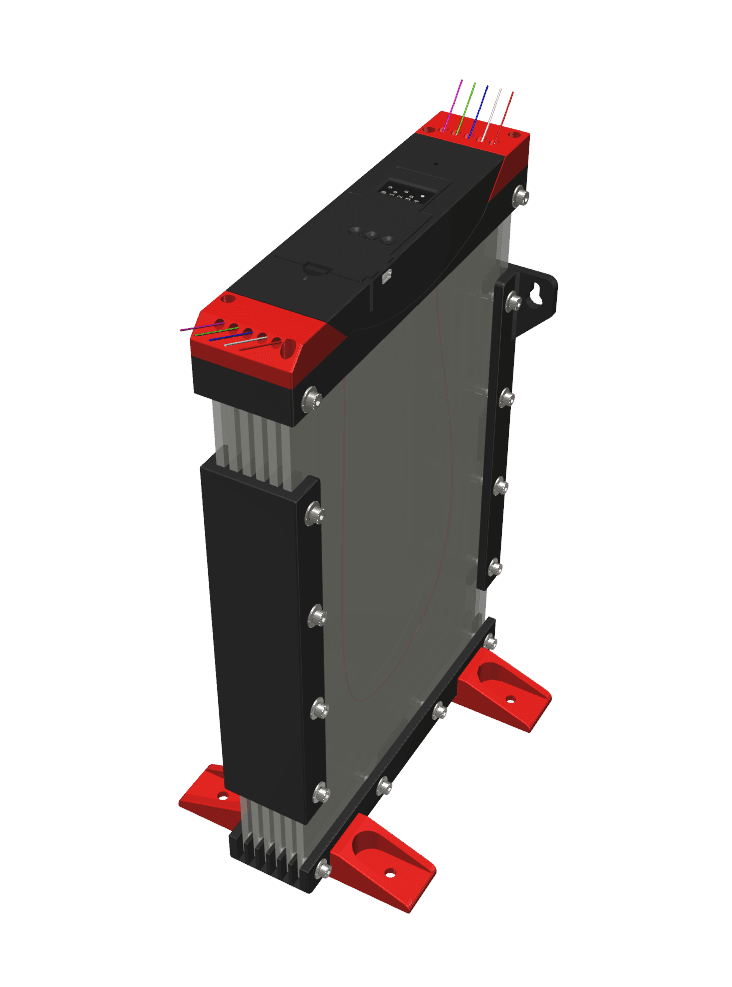
To get rid of this problem, I came up with yet another filament buffer. But this one's not just an ordinary filament buffer, it comes with quite some features:
- small footprint (327 x 210 x 55 mm)
- different mounting options
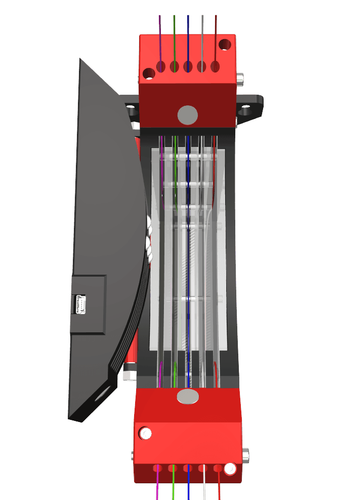
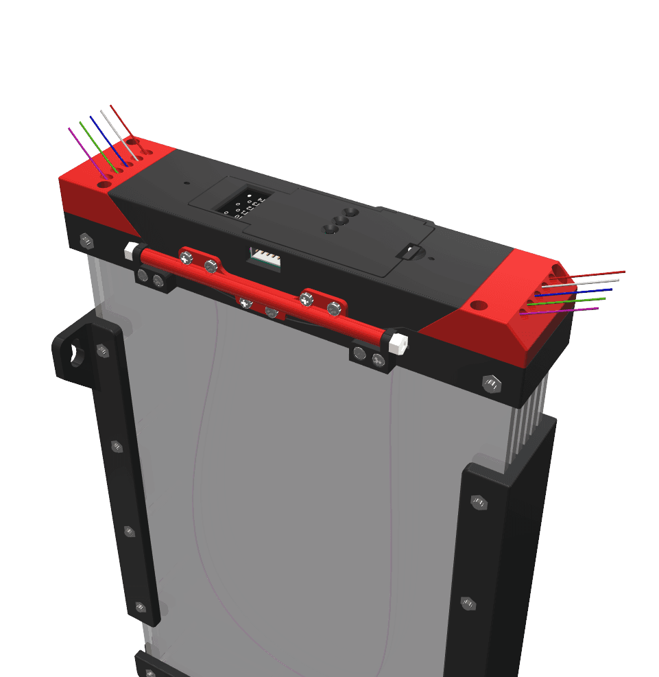
- integrated unique filament run-out sensor
- easy to load / unload
- up to 1000 mm buffering capacity per filament
- hinged or non-hinged
Here you'll find two very short videos of the device: https://youtu.be/0ec92D4GgwU https://youtu.be/mqZ_M43gkhc
OptionsYou can build this device either with or without the filament run-out sensor. With please use M05.stl and without M05a.stl. Mine was build to attach it perpendicular to a wall / cupboard (M02.stl/M03.stl). In order to mount it flat to the wall / cupboard you'll need M02a.stl and M03a.stl. If you rather prefer not to mount it somewhere, please use the S01.stl (printed twice) and M02.stl printed twice instead of M02.stl/M03.stl for a stand version. As for the hinge (H01/02/02): You don't have to assemble it, if you don't feel like since the top lid is being held in place by four strong Neodymium magnets.
BOMBeside the printed parts above, you'll need the following items:
- 6 Acrylic plates, 4 mm thick (Plate.dxf)
- 14 M4 x 50 mm screws
- 16 M4 nuts
- 14 M4 washers
- 4 Brass inserts M3 x 6 mm (inlet & outlet)
- 4 M3 x 12 mm screws (inlet & outlet)
- 1 Threaded rod M4 x 125 mm (Hinge)
- 2 Self-tapping screws 2.9 x 6.5 mm (Hinge)
- 8 Self-tapping screws 2.9 x 9.5 mm (Hinge)
- 7 Self-tapping screws 2.2 x 6.5 mm (OLED and Prototype board)
- 2 Neodymium cylindrical magnets 10 x 10 mm
- 2 Neodymium cylindrical magnets 10 x 1 mm
- 5 Steel balls 8 mm
- 1 Piece of ferromagnetic tape
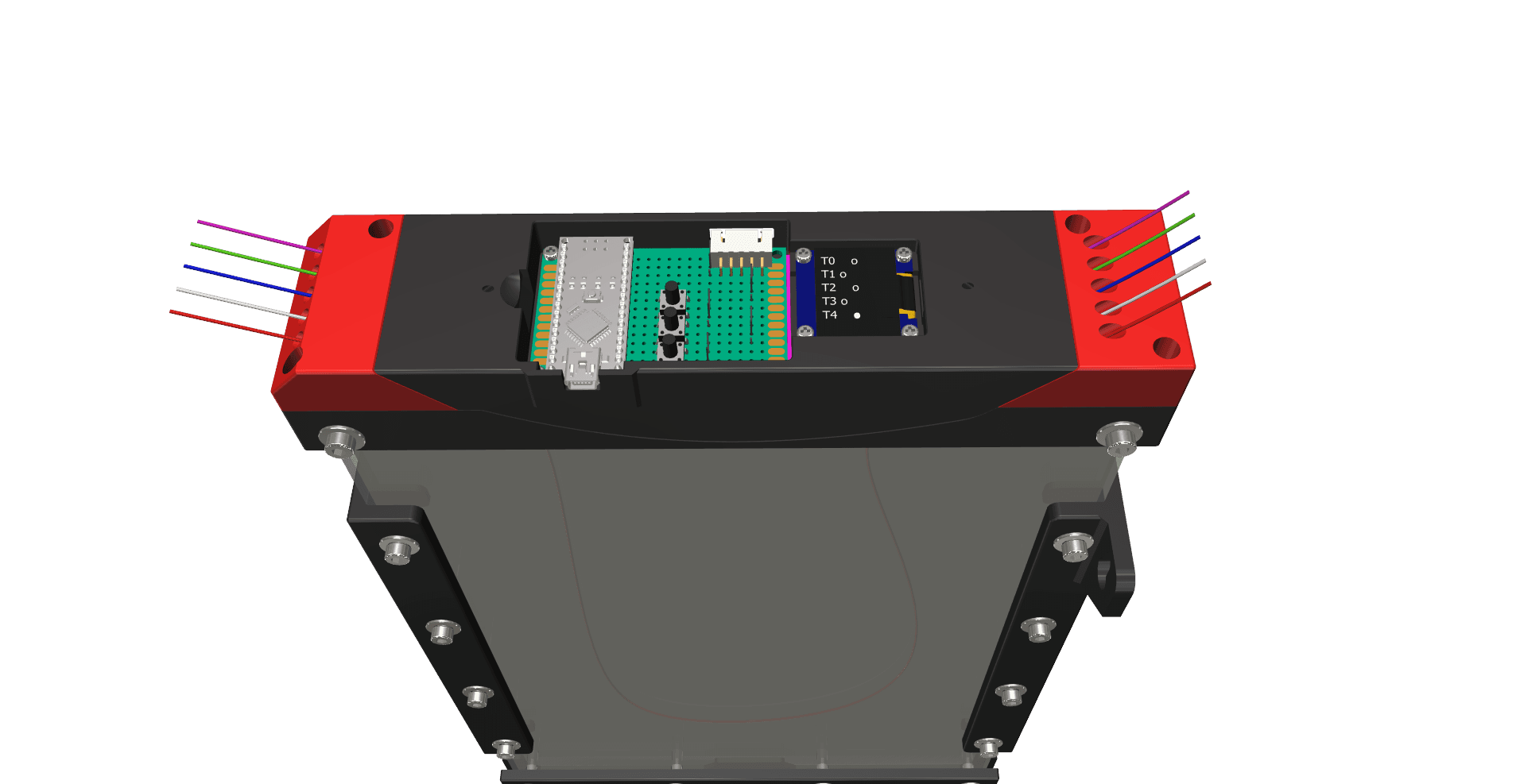
- 1 Sensor PCB
- 1 Arduino Nano V3
- 1 0.96" OLED (128x64 pixel, monochrome)
- 5 Linear Hall-Sensors A1326 LUA-T or SS495A
- 3 Microswitches 6 x 6 x 10 mm
- 1 JST-XH male/female connector (3 or 5 pin - later for future enhancements)
- and of course some wires and cables
Well, that's it for now.
Update 1Uploaded the firmware code to my Github repository. If anyone is keen to make a PCB for the electronics, let me know.
Update 2Added two stencils (Stencil-top.stl and Stencil-bot.stl) which allow you to cut out the side panels from a rigid foam board, for those who don't have easy access to a laser cutter.
Print out those stencils, cut 6 panels to size of 200 x 300 mm and use the stencils to drill the holes with a 4.5 mm drill and cut out the upper curvature with a stanley knife.
Video will follow.
Update 3I've designed and published a PCB for the SFB, which you can conveniently order on PCBWay. The updated schematics, as well as the Gerber files for that PCB can be found within the SFB Github repository.