
Model originally uploaded to Thingiverse at https://www.thingiverse.com/thing:4808256.
A Qidi X-Plus carriage for the E3D Hemera (Hermes) extruder, instructions, and firmware settings file.
Files:
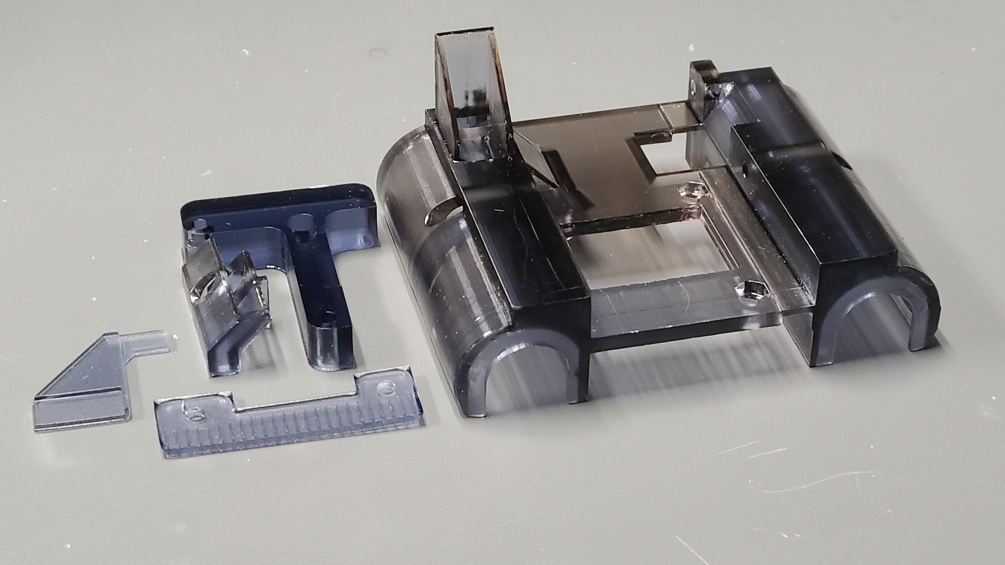
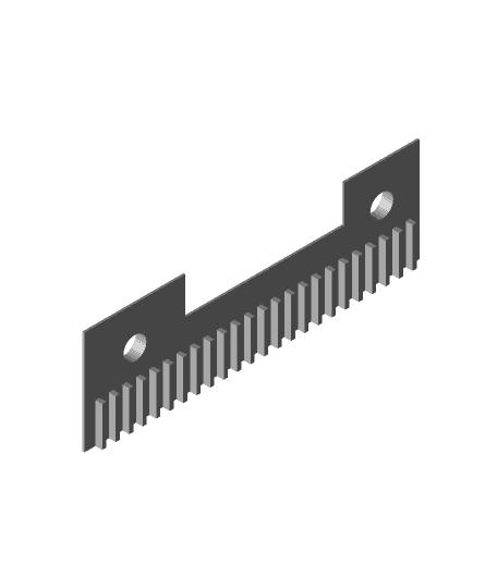
• CarriageV3.stl (carriage base, minus blower mount) • LimitSwitchPlate.stl (striker plate for x-axis limit switch) • PCBstandoff.stl (Qidi printed circuit board mount) • BeltClamp.stl (x-axis belt clamp) • CableGuide.stl (flex cable routing guide) • LEDholder.stl (optional general purpose glue on LED holder) • My X-Plus configFile for Hemera.gcode
The PCB, blower fan, stepper motor cable, and thermocouple were salvaged from my standard Qidi extruder (don’t use the thermistor from the E3D kit—it isn’t compatible unless you use adapter electronics).
Additional items needed: ¼ inch OD brass tubing for the filament cooling air nozzle, M3 screws (you will need to determine lengths yourself—sorry, I didn’t keep track), M3 nuts, CA glue, metal tubing cutter, double sided tape, other tools as needed for part clean up (sand paper, razor knife, ¼ inch drill bit, etc.).
I printed everything using a resin printer (Epax X1, in this case). I originally printed prototypes using my Qidi X-Plus, which produced useable parts, but with all the support issues and material limitations (shrinkage, deformation temperatures when hot end is mounted), I found resin was best. The resin I used was a 50/50 mix of Siraya Tech Blue and Siraya Tech Build.
Directions:
Once the supports are removed from the parts, you may need to clean out the bore of the bottom air duct using a ¼ inch drill bit in order for the brass tubing used as the air nozzle to press fit well. You can also try a sandpaper wrapped pencil.
Press and glue 2 M3 nuts into the top of the carriage to receive the screws that hold the belt clamp. You might need to clean the recesses with a hobby knife, depending on material shrinkage and how clean your print turned out.
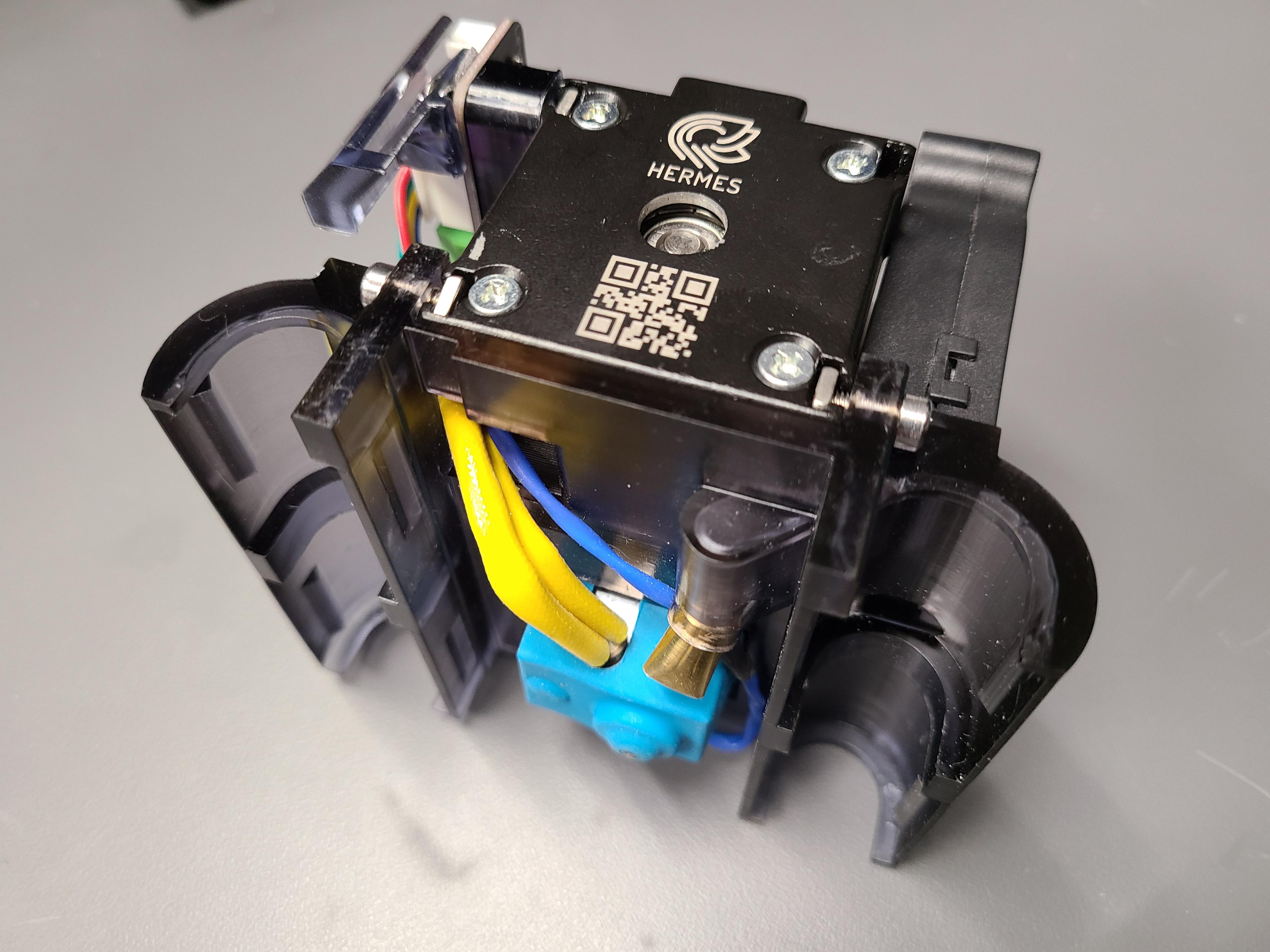
Mount the Hemera to the carriage next. Note that the screws barely engage the T-nuts, which is good, because you don’t want the screws to bottom out—that would break the T-slots on the Hemera (a commonly reported problem with screws too long). The holes in the sides of the carriage are for inserting an allen wrench (provided with the Hemera) to the recessed screws. Don’t tighten more than necessary, or you might deform the carriage. If you are worried about the screws working loose, use weak thread locker.
The fan mount is slip fit into the opening in the blower. When sized properly, the blower is held in place by friction (no screws or hold downs needed). Since different blowers have slightly different opening sizes and shapes, you will probably need to file the mount to fit first (I had to).
Next, mount the limit switch strike plate using CA glue. The strike plate has a relief that ensures proper positioning against the carriage. It will clear the fan, if the stock Hemera fan is used.
Clean the nut recess in the PCB mount, and press/glue an M3 nut into it. Use 1 M3 screw (not provided in the kit—you’ll need to find one the right length, because I can’t remember what I eventually scrounged from my hardware bin) to bolt the mount to the upper left T-nut of the Hemera (E3D provides extra T-nuts in the kit). Bolt the PCB to the nut you pressed into the lower left corner of the mount. Attach the cable guide and upper right corner of the PCB+mount to the Hemera using another T-nut + long screw. BE CAREFULL: If any screw is long enough that it hits the T-slot wall, select a shorter screw, or shim the screw head with washers.
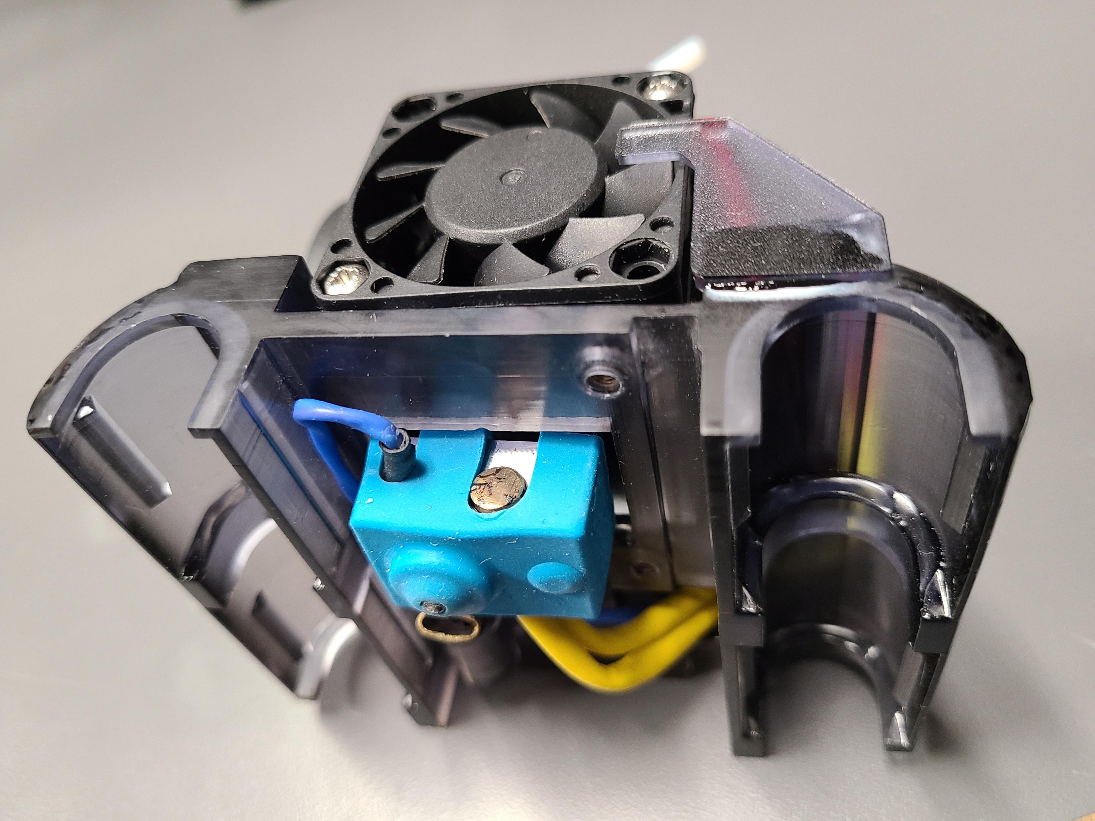
Take the heater provided in the Hemera kit, and cut the wires to the correct length for routing to the PCB.
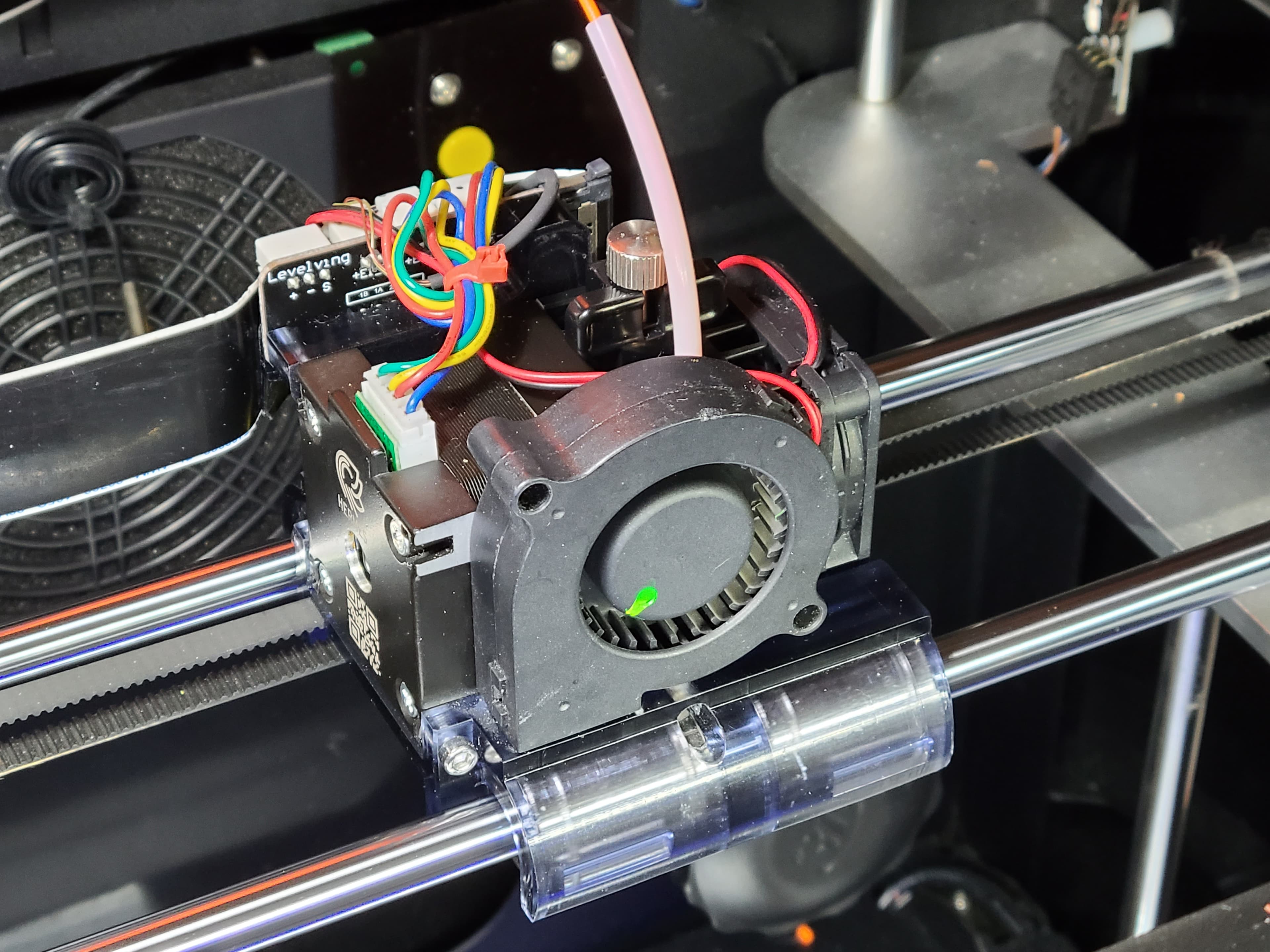
Modify the old Qidi stepper motor cable by removing pins and swapping them. Refer to the wire colors in the pictures for the wire swaps I had to do (the Hemera stepper is wired differently).
Route and connect the rest of the wiring. Use the old Qidi thermocouple (don’t use the thermistor from the E3D kit—it isn’t compatible unless you use adapter electronics). The Hemera fan connector is not the right type to fit the Qidi PCB connector, so you’ll need to cut and splice it to the old Qidi fan connector wires; or, you can do it the better way, and buy a new connector and crimp tool.
Finally, cut a piece of brass tubing for the nozzle, compress one end to flare it, and press the round end into the opening in the bottom duct of the carriage. Make any adjustments necessary to keep it at least 1mm above the extruder tip, or it will snag your prints. Note that the closer it is to the extruder or heat block the more heat will be radiated into it and transferred to the carriage (with enough heat, the resin may soften).
With printer power off and unplugged, remove the flex cable from the old extruder, remove the extruder from the old carriage, and remove the belt clamp. Pop the carriage off the 4 x-axis bushings and remove it. It is press fit to the bushings, so just work at it, and make sure you don’t put too much pressure on the rods, or they might bend.
Take your new Hemera carriage assembly, and snap it down onto the x-axis bushings. If by chance you carriage is loose on the bushings, you can shim them with small strips of tape until the fit is snug. Check to see if the bushings are binding or dragging (mine weren’t on my first prototype, but were on the next version, even though I did not change dimensions). This can be caused by surface imperfections in the bushing seats, dimensional issues with your print (shrinkage or warping), or crooked seating (remove and try again). If you just can’t eliminate binding, loosen the screws holding the Hemera to the carriage, and see if the problem goes away (screws too tight, and it may flex the carriage). Finally, you can try CAREFULLY heating the carriage center section with a heat gun while it is installed on the x-axis rods—the material may relax to the stresses imposed by the rods, then harden in a more accommodating position. Use discretion—not all plastics and resins behave the same way.
Screw the belt clamp against the teeth of the belt, and make sure the belt is secure, and the carriage moves properly by hand. You might have to loosen the x-axis stepper, and reposition it to get proper belt tension.
Connect the flex cable, power on, and check the System Info screen for anything unusual. Temperatures should read somewhere around 25C.
Heat the extruder, then run some filament through it. It will extrude very slowly, because you haven’t adjusted e-steps yet. If it chatters, the stepper wiring has a problem.
Assuming all is okay up to this point, you should save your firmware settings before changing them. To do this, create at text file with the extension “gcode” with this command in it, and print it from the usb stick:
M8512 'configFile.gcode' ; Download current config to file
Your machine’s default settings will now be in configFile.gcode on your USB stick.
Save the original file, then apply the following edits to make a new file (name it [whateveryouwant].gcode). You can reference my settings file for what I ended up with. VERY IMPORTANT NOTE: My file has settings and customizations that are specific to my machine, so be careful, and understand the changes you make to your settings before using them! There are several references on Thingiverse and other places that help explain. Here are good starting values:
M8011 S0.002523; CALIBRATED E-STEPS IN MM/STEP FOR HEMERA—Should be universal, but test and fine tune.
M8024 I287; Max X (right limit switch X-value) adjusted for Hermera extruder carriage (DETERMINES ZERO LOCATION OF BED LEFT EDGE)—Yours should initially be around 287, but observe where your x-axis zero location ends up, then adjust.
M8025 I200; Max Y (rear limit switch Y-value) adjusted for Hermera extruder carriage (DETERMINES ZERO LOCATION OF BED FRONT EDGE)
You might also need to change the maximum Z-height of the bed if your adjustment screws and springs don’t position optimally when you run bed leveling. This carriage puts the Hemera extruder tip slightly higher in the build space (a good thing—allows more build height). When adjusting this number higher, pay close attention to how much space is left between the z-axis bushings and the frame when the build plate is raised—don’t let it hit the frame. In my case, for example:
M8026 I208; MAX Z (BOTTOM LIMIT SWITCH Z-VALUE) (DETERMINES MAX BED TRAVEL AND MAX BUILD HEIGHT)
Put your new file on USB stick, and print it to set new values.
You should do a full extruder stepper calibration, and calibration cube print. The e-steps given above are from my own calibration effort, and should get you close.
I found that I had to reduce extruder temperatures for all my filament types by 10-15 degrees, because the E3D extruder heated more efficiently. That was okay with me, since I had to previously set them 10-15 degrees higher than recommended to get the Qidi extruder optimized.
NOTE: The Hemera’s stepper motor operates best at higher nominal current than the Qidi motherboard produces. Luckily, I’ve haven’t observed under extrusion nor missing extruder steps after making the change to the Hemera (probably due to tripling the torque from gear reduction), but it might cause skipping at high feed rates. However, I believe there is a way to increase the current, if needed. This is an advanced, UNPROVEN modification, so don’t take it lightly. I found what I believe are stepper current sense resistors on the motherboard (next to the E2 stepper connector, chip resistors marked “R100” for 100mohms). If I’m correct, they are used to measure the winding currents for comparison to the programmed reference voltage (which is hidden from us due to Qidi using “proprietary” firmware). I suspect either changing these resistors to a lower value (R080), or paralleling something like 0.5ohms, will “trick” the drivers into sensing less current than reality. I suspect this is the case, but never made the change, since the Hemera works well for me as is. If you do try this somewhat risky mod, make sure you mount a better fan blowing directly down the length of the heatsink fins. There are 2 of these resistors next to each stepper connector on the motherboard, corresponding to 2 motor windings. According to information I found in forums, plus what Qidi and E3D have told me, here is what I figure:
• Qidi stock driver current: Unknown—somewhere between 0.6A and 0.8A • E3D Hemera “motor current”: 1.33A (from E3D datasheet—probably the maximum rating) • Driver current with 0.5ohm resistors in parallel: increases from 0.72A to 0.96A (20% more current)
If you change your Qidi X-Plus or X-Max to use the E3D Hemera, please post questions and comments here. I will try to be helpful. I go through busy periods, and might not answer for a while, so please be patient.
As of the original date of this posting, I have put hundreds of hours on my Qidi X-Plus E3D Hemera mod with no issues, only with excellent results. In my opinion, it increases the reliability and capability of the machine by an order of magnitude, and I highly recommend this upgrade.