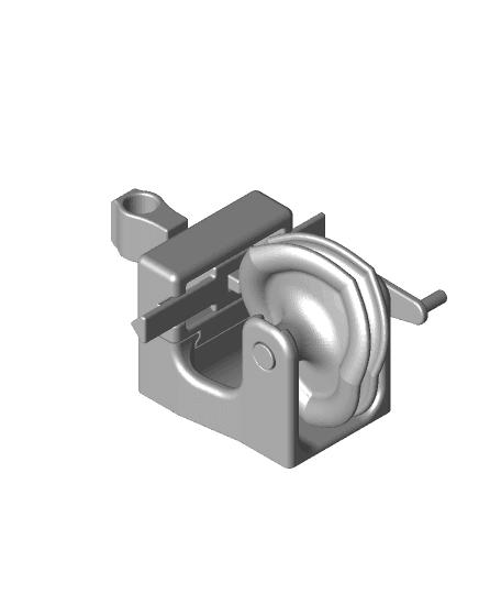
Complex Barrel Cam Shape Drawing Machine
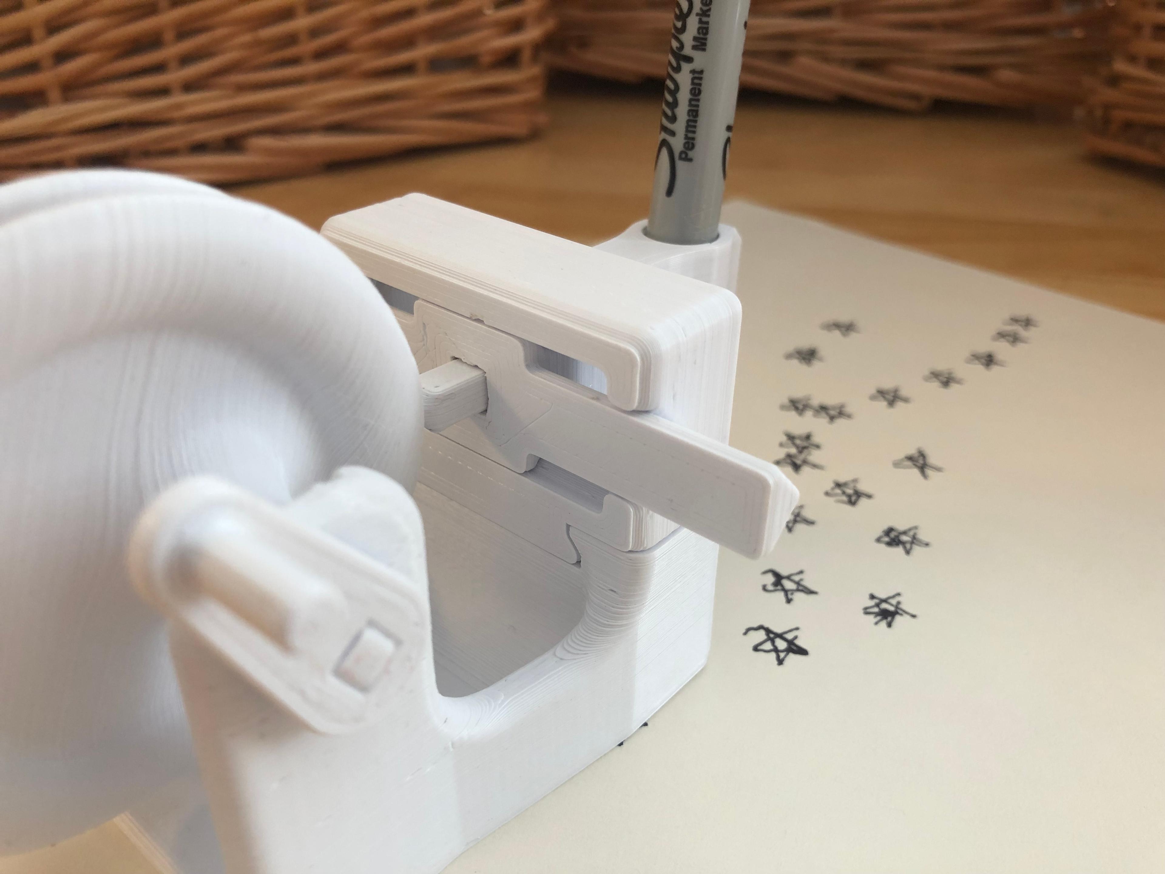
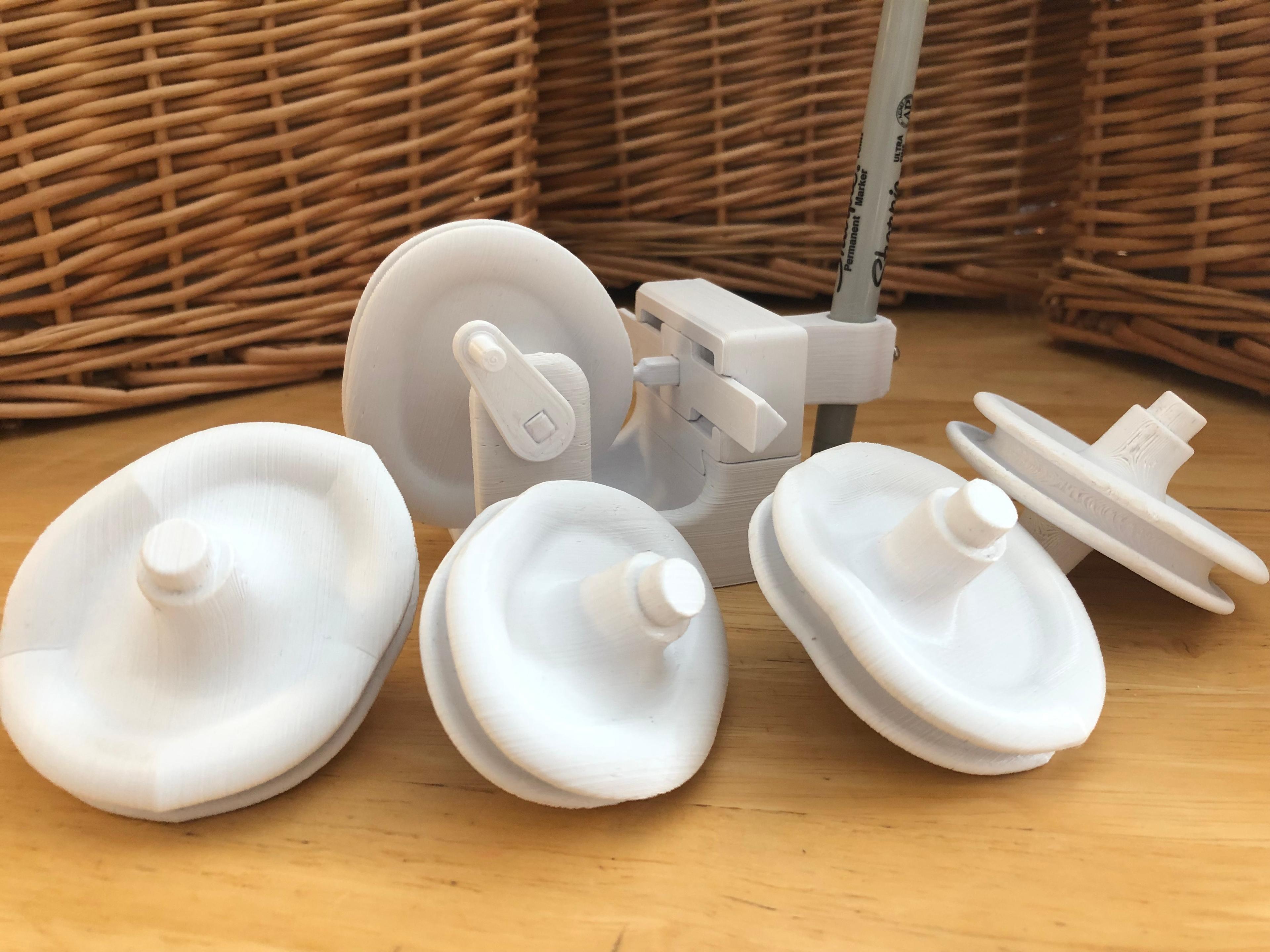
byDaveMakesStuffThe “Complex Barrel Cam Shape Drawing Machine” is an advanced project that demonstrates the mechanical potential of barrel cams to encode and generate complex movements. Included here are files to make barrel cams for a circle, square, infinity sign and star.
See here for video: https://youtu.be/DdSJuxJodQM
The barrel cams are designed by plotting shapes from an xy plane onto a cylinder. Movement in the x direction is plotted helically along the length of the cylinder. Movement in the y direction is plotted along the radius of the sphere. When the cylinder is rotated, the follower and piston reproduce the shape back onto the xy plane.
Here are the parts you will need to print:
Print one of each “Base,” Crank,” and “Crank Connector.” These are all straight forward prints.
The “Print Surface Stand” is optional. It raises the printing surface bringing the pen closer to the paper and reduces the amount of error caused by a wiggly pen.
Print one or both of the “Followers.” The “Barrel Cam Infinity” requires the longer “Follower 40mm,” all the others use “Follower 35mm.” Use a small file to remove any imperfections around the ball, but try not to reduce the diameter of the actual ball or it may slip out of the barrel cam track during use.
Print one “Pen Holder.” Use one small screw to secure the “Pen Holder” on to the “Follower,” Use a second small screw to hold the pen in place.
The hardest print in this project is the “Slider.” The slider is actually two separate objects printed in place. The reason for designing these together is that the tolerance and fit must be so precise that it cannot be reliable reproduced by gluing pieces together or other methods of connecting. When you print this piece, even though the two objects aren’t touching you will likely get some small adhesions that hold the pieces together then you remove it from the buildplate. Hold the piece on its end off the side of a table, place a piece of wood or metal on the top of the center piece, and give a few sharp taps with a hammer. The piece will come loose, but you will need move it back and forth forcefully a few times to smooth out the surfaces. The piece should move freely and easily.
Print out the “Barrel Cams” that you would like. The objects are positioned optimally in the files, but you will need to use supports. “Tree Supports” in Cura work well.
Add a thin layer of Vaseline to surfaces that slide against each other and assemble the pieces.
Slide the “Slider” mechanism onto the “Base” first.
Next, insert the “Follower” into the groove of one of the “Barrel Cams.” You will notice that there are two flat surfaces on the ball of the follower that allow the ball to insert into the groove in one direction, but lock into place with a 90 degree turn. Turn the follower 90 degrees to lock it into the barrel cam and then insert through the square hole in the slider.
Spread the uprights on the base and snap the barrel cam axle into the holes.
Assemble the “Crank” and “Crank Connector” using a bit of glue to hold it tight, then press fit the other end of the “Crank Connector” into the square hole of the “Barrel Cam.”
You will need to use a pen that has minimal friction against the surface of the paper. An “Ultra Fine Point Sharpie” works well.


