

Vyper_Stronger_Filament_Sensor_Mount_45_Degree.stl
REMIXED FROM: https://www.thingiverse.com/thing:4927953
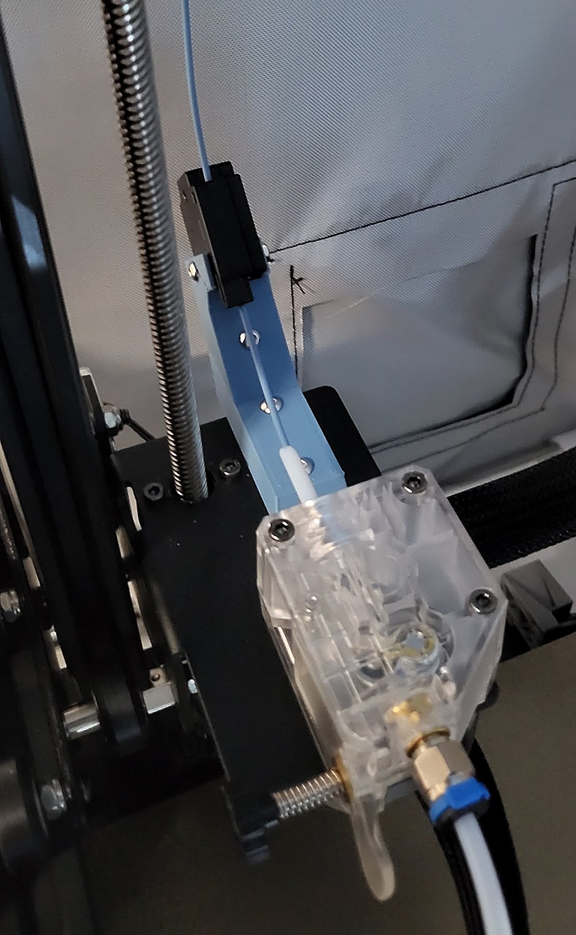
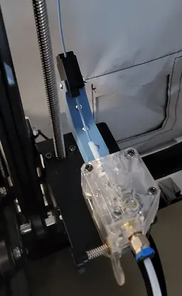
This is my remix of the stronger Vyper filament runout sensor adapter, modified to be at a 45 degree angle for top-mounted filament configurations.
Due to enclosure size restrictions, I had to mount my filament spool on the top of the gantry. I didn't like the 45 degree adapter options available, as the filament runout sensor is attached by a single screw on a flimsy plastic arm out of the box. I had some concerning noises during retractions.
The following modifications were made to the original design:
- Extended sensor mount point and angled upwards 45 degrees
- Added additional M3-sized (3.5mm) screw hole on 45 degree offset
- Expanded size of filament sensor arm channel (it's now enclosed)
- Flattened bottom to eliminate need for any supports
To install, I used the following:
- 2 x M3x20mm screws
- 2 x M3x16mm screws
- 2 x M3 nuts
To attach to the Vyper:
- Completely remove existing filament runout sensor, including the metal tab it attaches to (2 screws total).
*** Note that this will drop the X-axis gantry control board below, as it is only held in place by those 2 screws. Be careful!
- Attach the filament runout sensor to the printed adapter using the 2 M3x20mm screws, and 2 M3 nuts.
-
One screw will go through the normal mounting hole, the other will go through the side hole that was previously unused.
-
Don't secure either too tight, just snug!
- Attach the entire thing back to the X-axis gantry using 2 M3x16mm screws. It should sit flat on the gantry plate, and the screws should hold the control board snugly.
Note that I had previously cut short my Bowden tube going into the extruder assembly, so I'm not sure that's a necessary step for everything to fit correctly.
Vyper_Stronger_Filament_Sensor_Mount_45_Degree.stl

Penguin - Hatchling

Ice Cream Narwhal - Hatchling

Skeleton RattleSNEK

Star Cookie Tadling

8x8 MU - MultiBoard Octagon Plate - 4x Ironing Stack
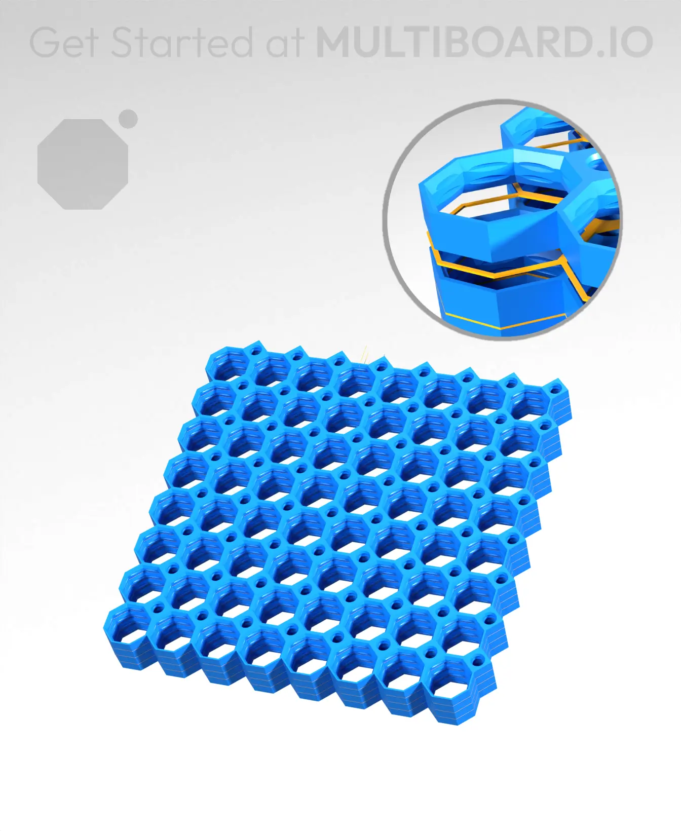
8x8 MU - Center Grid Interfitted - MultiBoard Octagon Plate - 4x Multi-Material Stack

Baby Candy Corn Dragon
Lizard - Hatchling

Crystal Gem Dragon - Hatchling

Alicorn - Hatchling
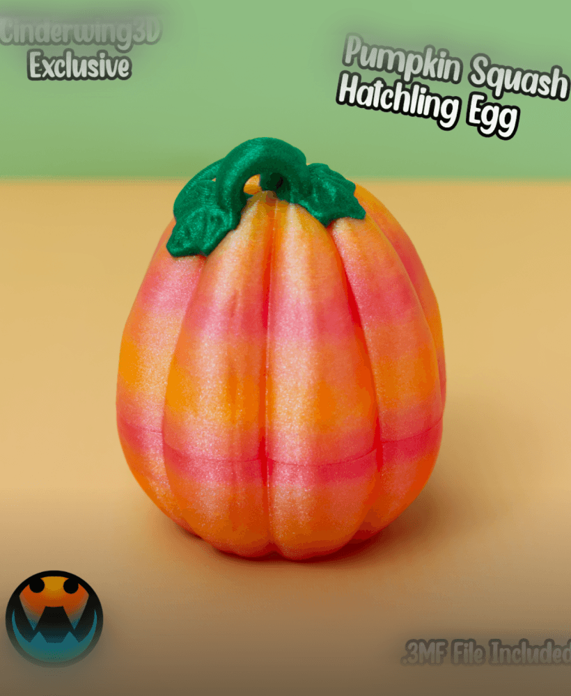
Pumpkin Squash Hatchling Egg
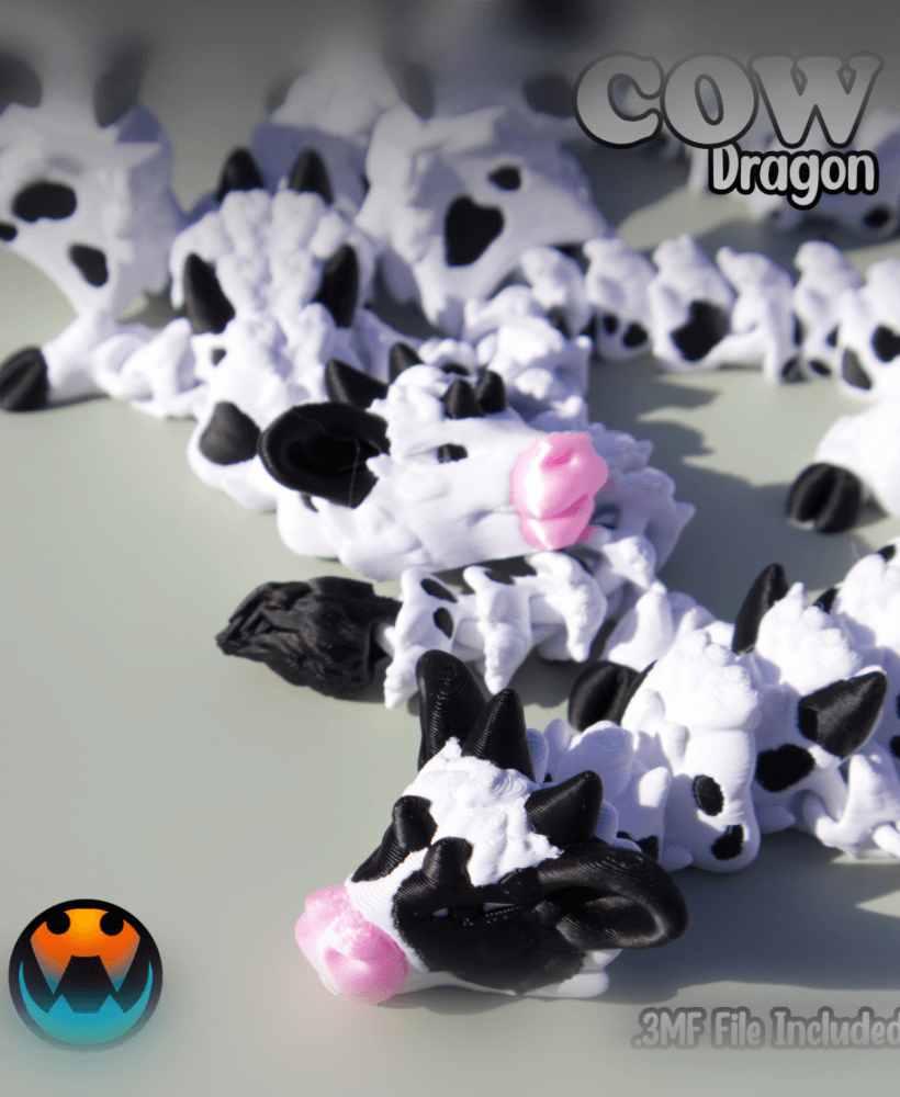
Cow Dragon

Tiny Cookie Heart Wyvern & Dragon
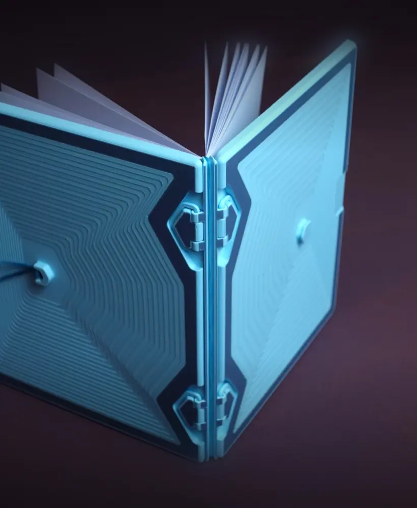
Notebook with pencil case
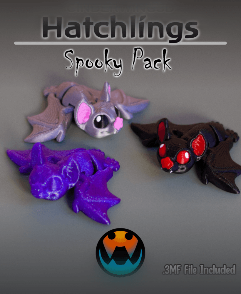
Bat - Cinder Hatchling
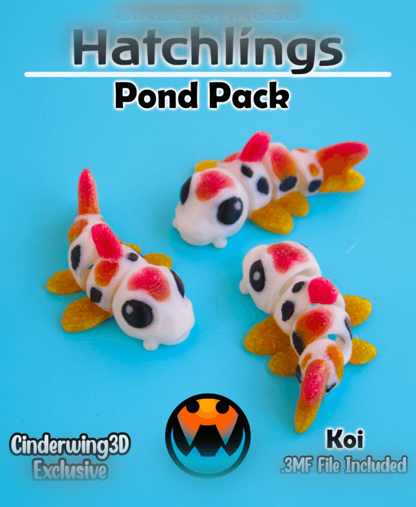
Koi - Hatchling
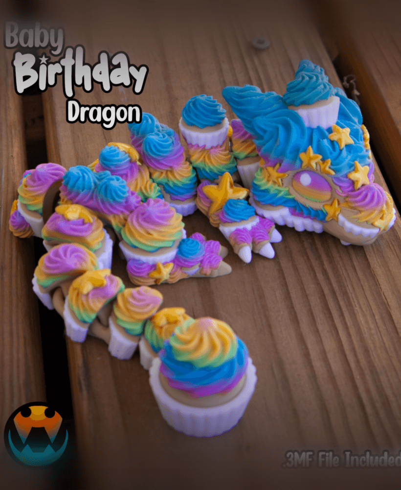
Baby Birthday Dragon

PlayBook'd - Hangman
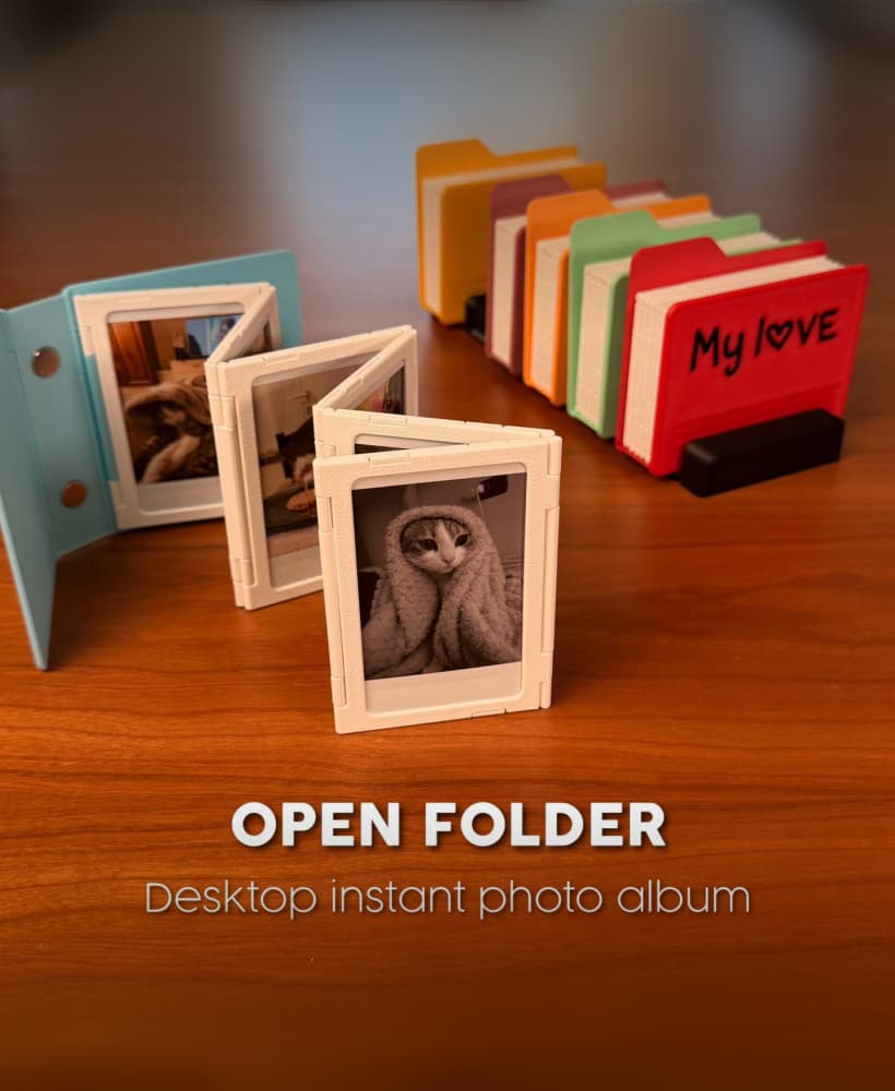
OPEN FOLDER | DESKTOP INSTANT PHOTO ALBUM
