


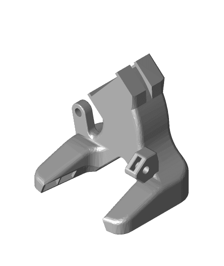
Railcore bed pivot offset laser calibration aid
Model originally uploaded to Thingiverse at https://www.thingiverse.com/thing:5338928.
<b>Warning: This project, as designed, calls for a 650nm 5mw laser. NEVER POINT A LASER AT ANYONES EYES, INCLUDING YOUR OWN, EVER! That means using proper safety equipment and being aware of reflective surfaces.
BE SMART. BE AWARE. BE SAFE!!! Even low power lasers can cause retinal damage.
BUILD THIS AT YOUR OWN RISK!</b>
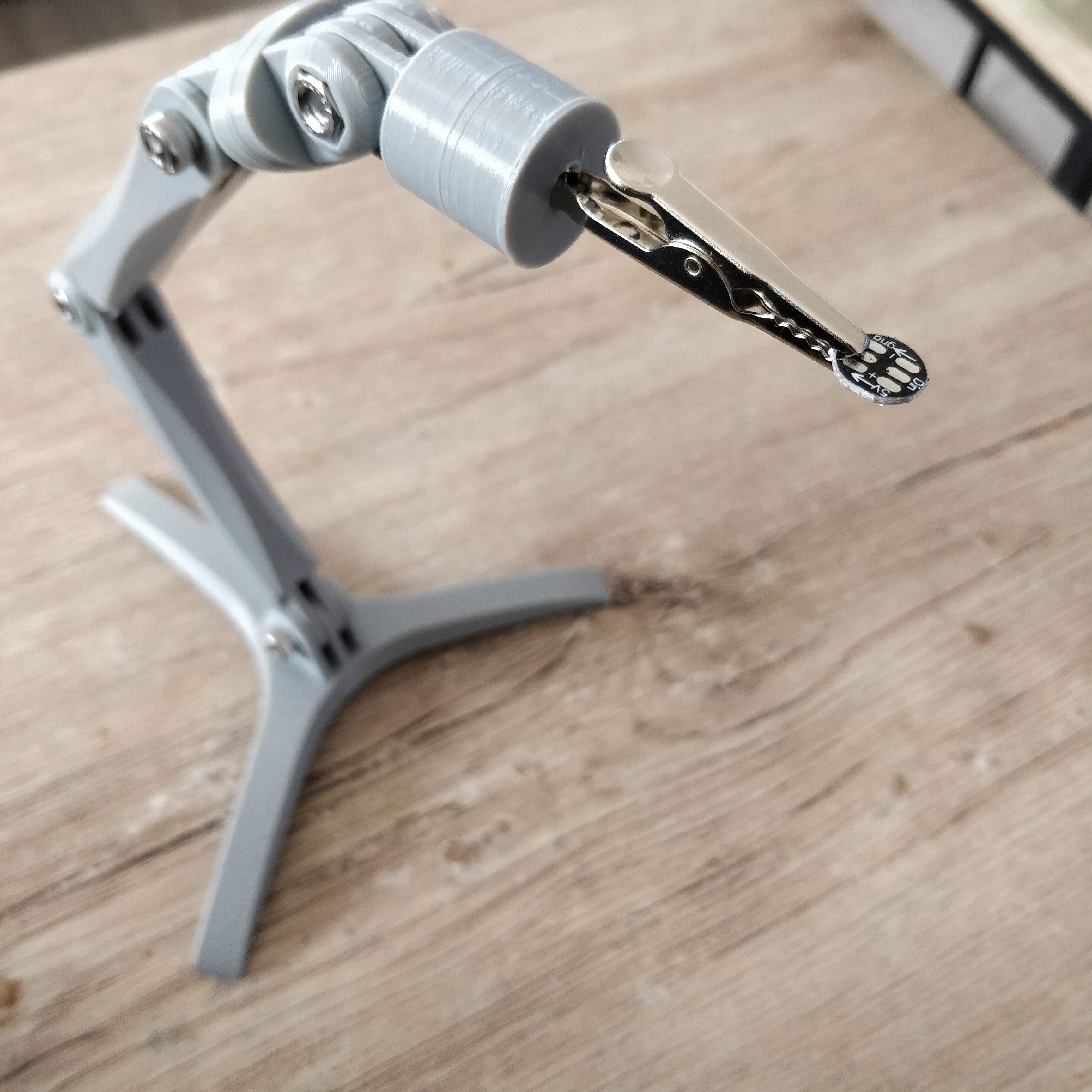
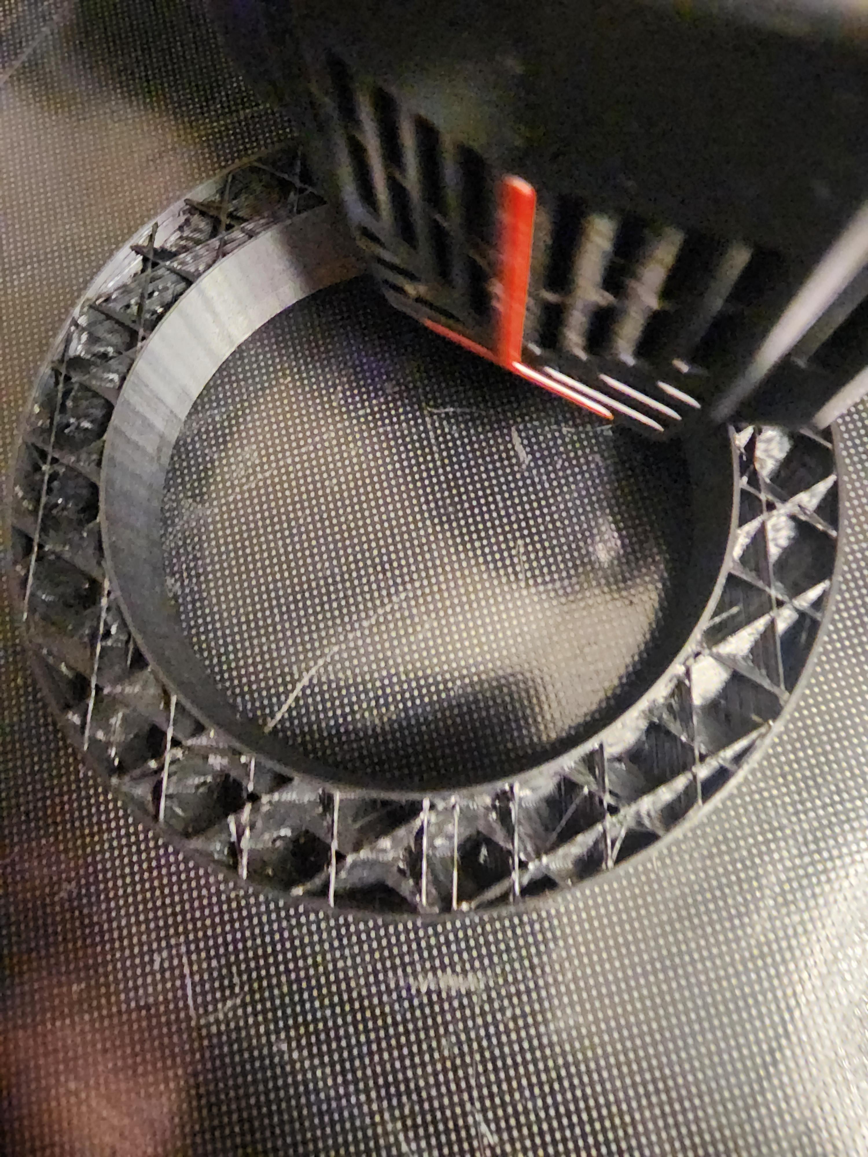
Tony Akens was kind enough to make a video on how to properly acquire calibration distances between each of the bed pivot points and the nozzle. While I found the video super helpful, I got frustrated trying to work my hands and eyes around the print head to take measurements and make markings.
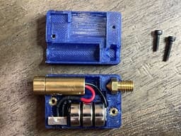
Note: I am NOT including assembly instructions for this project. If you cannot figure it out from the photo and parts list, you probably should not be building this. This project requires knowledge of how to use all tools and parts necessary for completion in a safe manner.
Caveats: Designed for use with E3DV6 hotend. May work with others.
Parts list: 1 x 650nm red laser protection goggles 1 x M6 nozzle 1 x 2 position SPDT slide switch 1 x 5mw laser diode cross unit
<b>IF YOU BUY A DIFFERENT LASER, MAKE SURE YOU GET THE CORRECT SAFETY GOGGLES!</b>
3 x AG13 or compatible 1.5V batteries 2 x M2x4x2.0 heatserts 1 x M2x10mm socket cap screw (laser-side hole) 1 x M2x8mm socket cap screw (nozzle-side hole) 1/16" (or metric equivalent) heat shrink tubing Nickle strips for battery terminals Short length 22AWG wire Solder Flux
Tools: 1.5mm Hex key for M2 socket screws Soldering iron Heat gun Cutters to trim terminal strips Right angle tool to check alignment of laser-to-housing (prior to mounting) and housing-to-print bed.
How to use:
- Watch the video.
- You will still need to measure the offset to the z-probe as described in the video. The laser tool is too tall to make it easy to measure the distance to the probe. I found that taping a piece of cardboard to the bed and jogging the nozzle down to make in impression or hole in it worked better for me than trying to mess with a pencil.
- Remove nozzle
- MAKE SURE HOT END IS TURNED OFF AND THAT IT HAS COOLED TO AMBIENT TEMPERATURE!
- Lower bed and replace nozzle on print head with alignment tool.
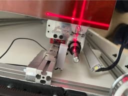
- Ensure cross is aligned in x/y with bed by tightening or loosening the tool. Alignment is more important than being tight. A right-angle tool placed against the edge of the bed is helpful in aligning.
- Move print head in x/y per video above.
- Center on pivot points using laser and measure from center of cross to pivot points and take notes.
- complete for all 3 pivots
- replace tool with nozzle and properly tighten
- check / remeasure Z-offset
- Make your config.g updates
Railcore bed pivot offset laser calibration aid

Z-Offset Calibration
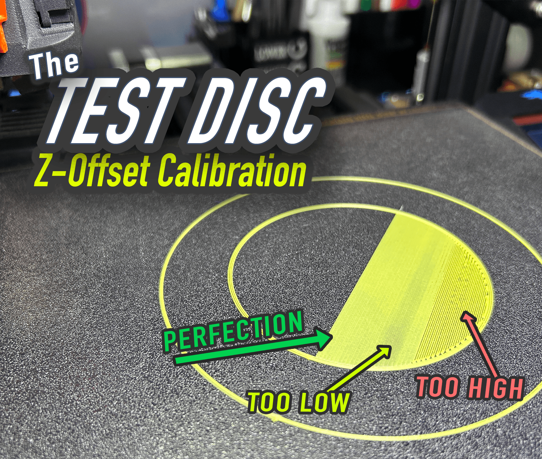
THE TEST DISC | Z-Offset Calibration Disc
Dual hotend offset calibration

Ender 3 bed level test (dual extrusion) / offset calibration

Bed Calibration level and Z-offset
Raised Quad Snap (DS Part B)

Folding Scalpel Pocket Knife v2.1

Raised Double-Sided Snap (DS Part B)

First Layer Squish Calibration Tool
Calistar (formerly Fleur de Cali) - Open source printer size and skew calibration

Folding Scalpel XL v2.1 (for #60 Blades)
Soldering Clamp
Prusa MUTANT Upgrade Kit (for MK2.5S, MK3S, MK3S+)
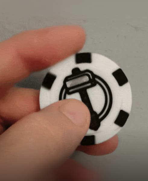
SpinMaker Chip – Customizable Spinning Maker Token

Prusa MUTANT Upgrade Kit (for MK2.5S, MK3S, MK3S+)
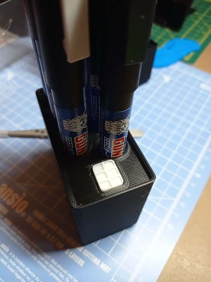
Gundam Marker Gridfinity Bins
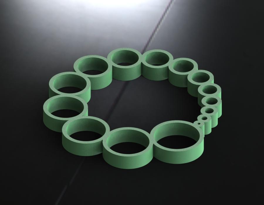
Hole Test
Chinese Diesel Heater Muffler Collection
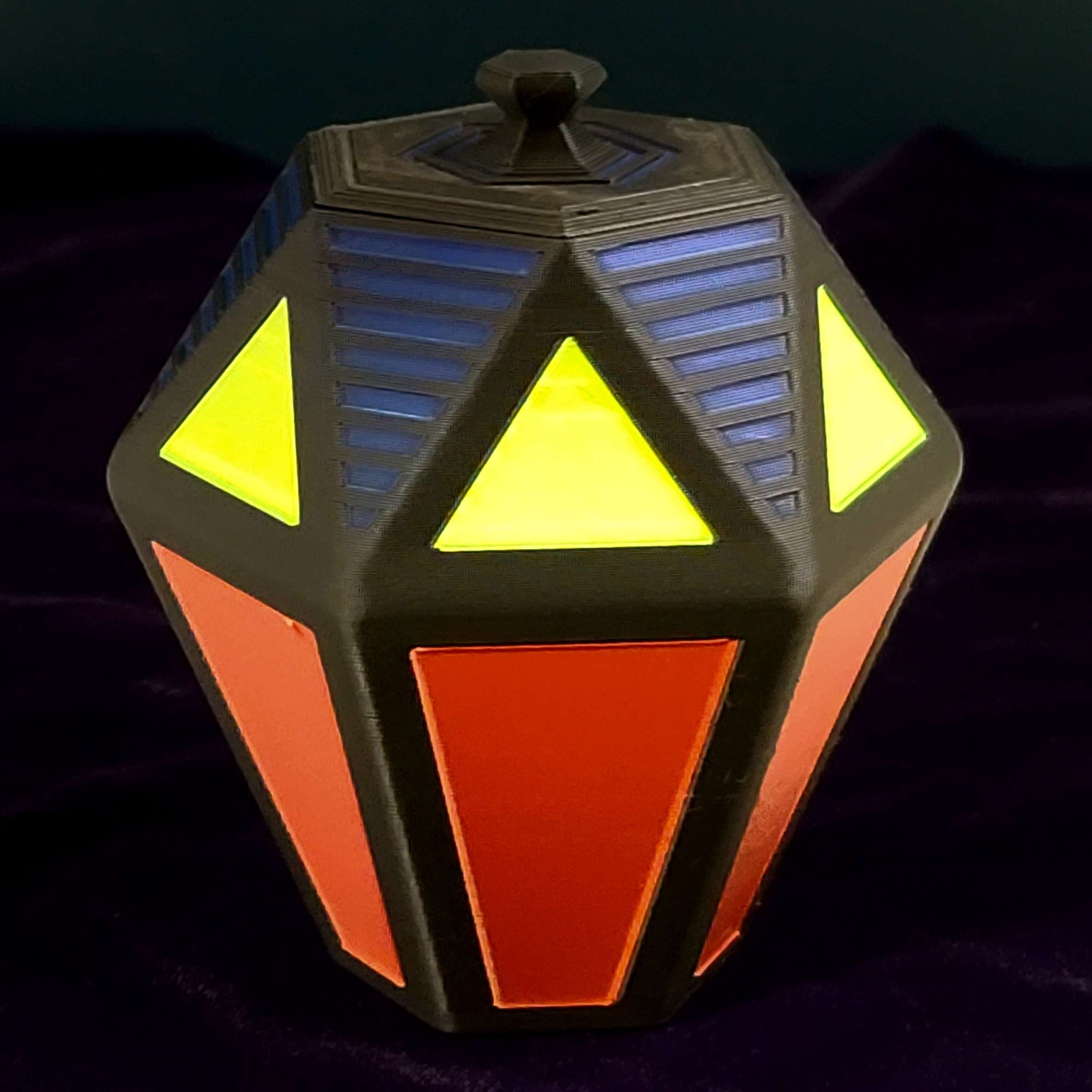
Futuristic Faceted Container / Stash Jar