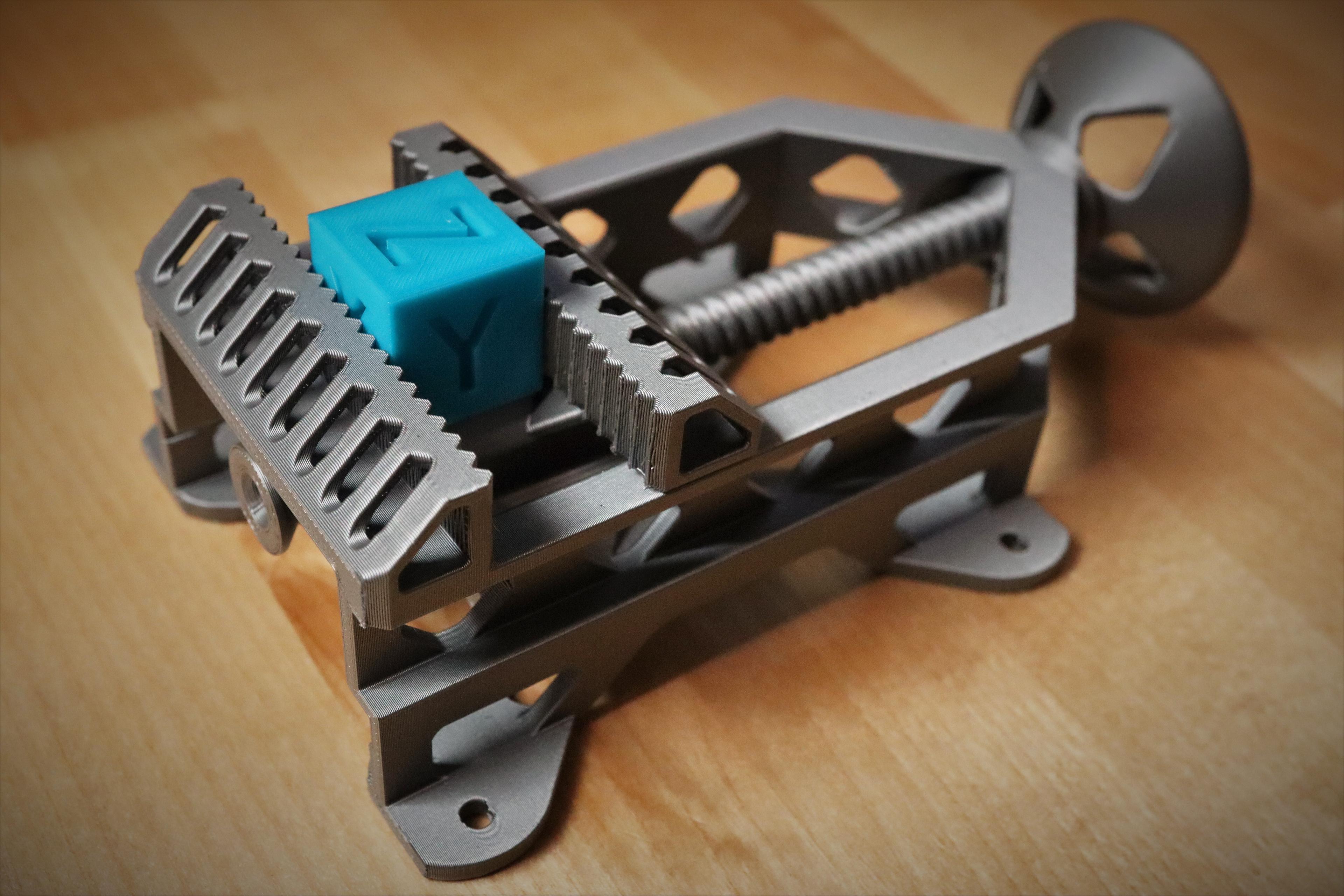
Mantis Clamp Vise
Model originally uploaded to Thingiverse at https://www.thingiverse.com/thing:5918381.
One of the key elements of the original Falcon Clamp not preserved in the Mantis Clamp is a compound planetary gearbox featuring fused sun gears. Indeed the very thing was a contrived application of this concept.
The two-layered planetary system of the "quick print" version was also only intended for calibration and demonstration. As you will find, the planet gears will twist under load and the clamping force will be quite limited. I've included a similar "demo" version here which is actually not too bad with the third layer of the stand providing some stabilization.
Three planetary layers allows this twisting force to be balanced out and more torque to be applied. Similarly, the integrated plane bearing surface provides additional stability.
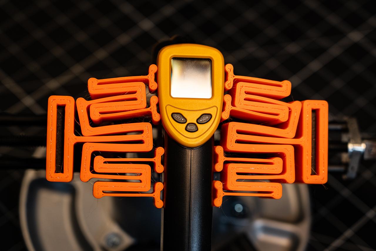
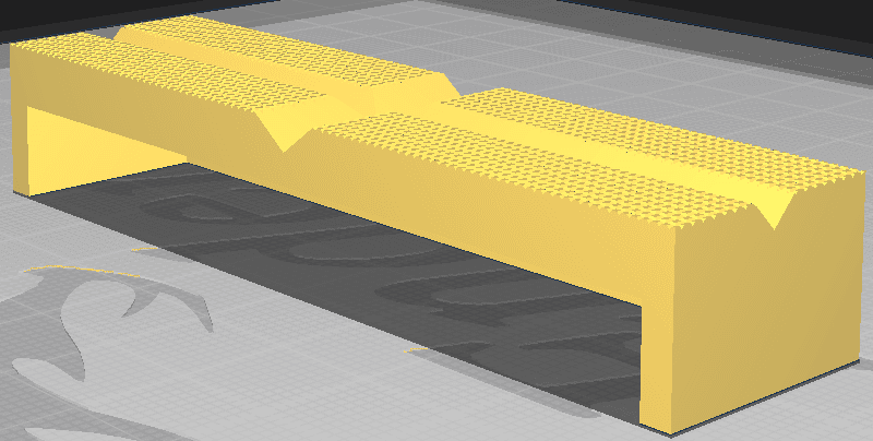
While we're at it, lets add a 4'th layer with a gear ratio approximately half way between that of the two jaws to which we can mount a self-centering stand. It's starting to look a bit Draculaesque.
It’s a bit over the top, coming in at around 7 hours, but I’m not going out of my way to make it as small as possible (not aiming for a torture test), but keep in mind there is some post-processing required to separate the ring gears with a sharp edge. Also check preview when slicing to ensure the 1-layer gaps which separate the rings are preserved.
Use a clearance gauge. I’ve used 0.5mm tolerances which are a bit looser than my usual 0.4mm. It should be tight to minimize gear slop but be able to crack apart cleanly. If you have trouble, lower temperature or extrusion rate can help or negative horizontal expansion can widen up the gaps. You can always go BIG!
Afterthoughts: Needs some more attention to post-processing. Maybe not as aggressive herringbone twist and some more clearance (updated). I am well practiced in knowing how much force I can get away with applying but newcomers will find this frustrating. I do like a nice, tight gearbox, though. A 14mm socket came in handy to get a little more leverage for the initial break-in. Once I got the gears moving, I was able to turn it in the close direction until it bound up. Then a few taps of the rubber mallet to help the outer jaws close. Then turn the gears a little more. Repeat. Use patience and proceed slowly. A dab of Vaseline really helps.
I usually end up with a little gear tooth overlap using this involute gear library. Tweaking depth ratio and pressure angle gives a little room for adjustment. The model is not suitable for customization in its current form with a lot of hard-coded and fudged measurements.
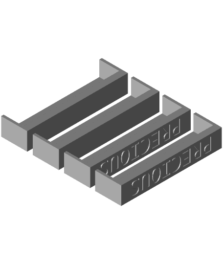
Mantis Clamp Gridfinity Stand
Clamp-On Vise - Fully 3D Printable
Atomic Vise - 100% Printable Desk Mount Vise
Flexure Fractal Vise Jaws - V6

Centre Drill Jig for Tubes / Round Bars
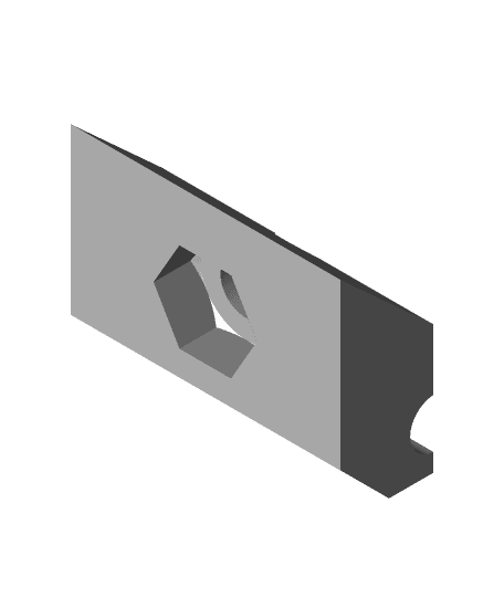
shop_vise_jaw_pads.stl
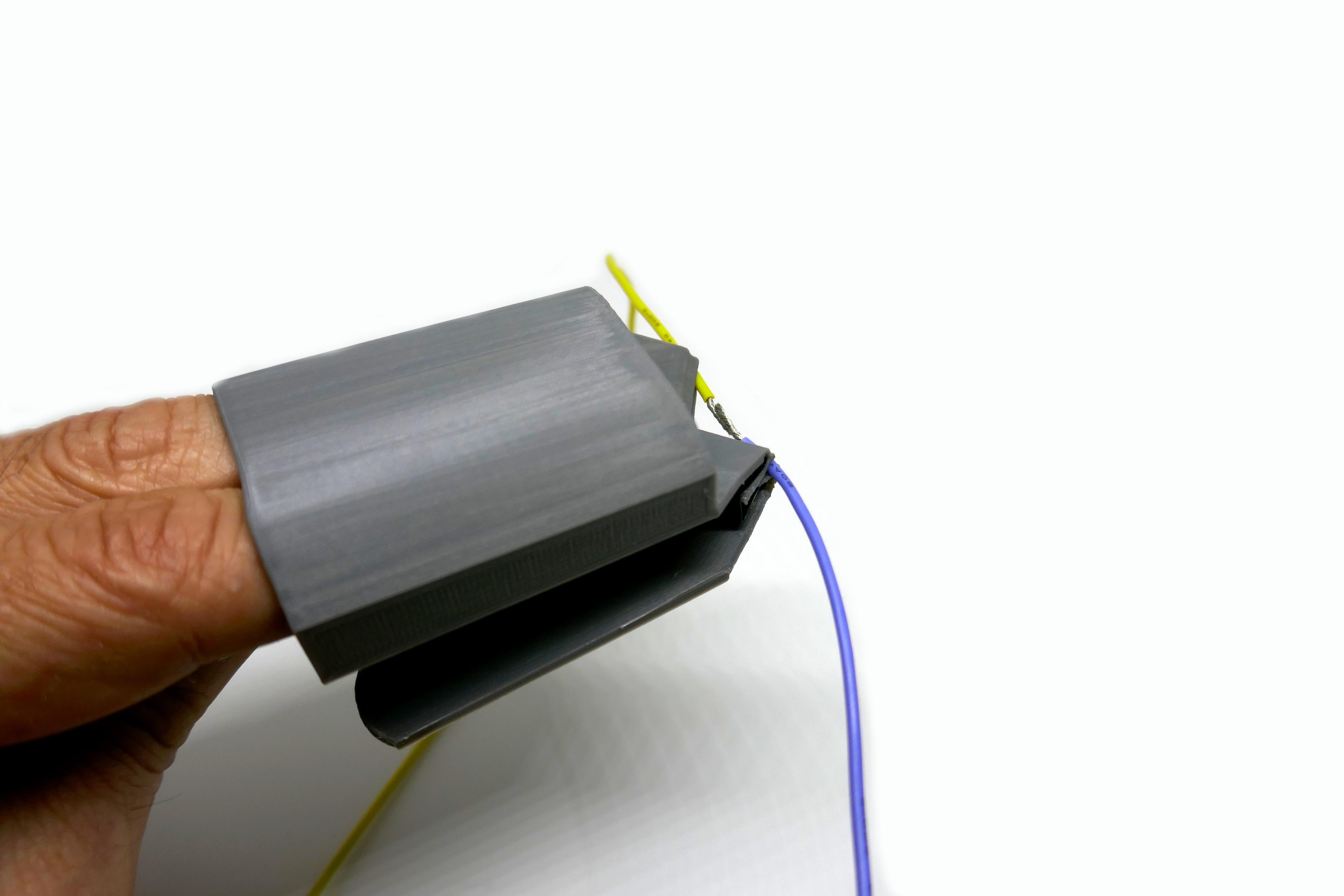
F!NGERV!SE - A SMALL WEARABLE VISE
Simplicity TV Mount Clamp
3" Bench Vise Magnetic Soft Jaws Multi-Grooved
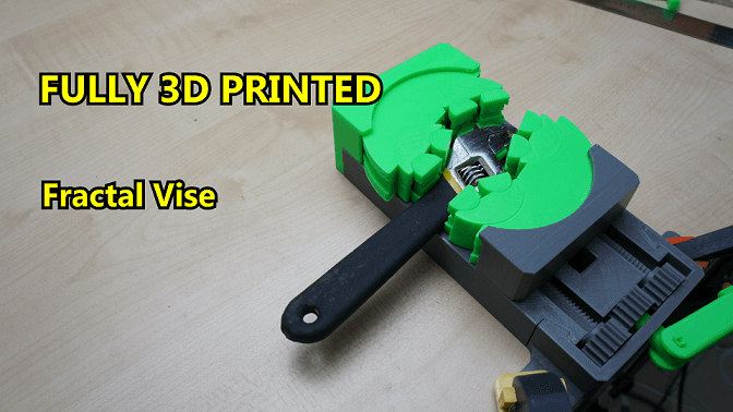
Fully 3D Printed Fractal Vise (Small)
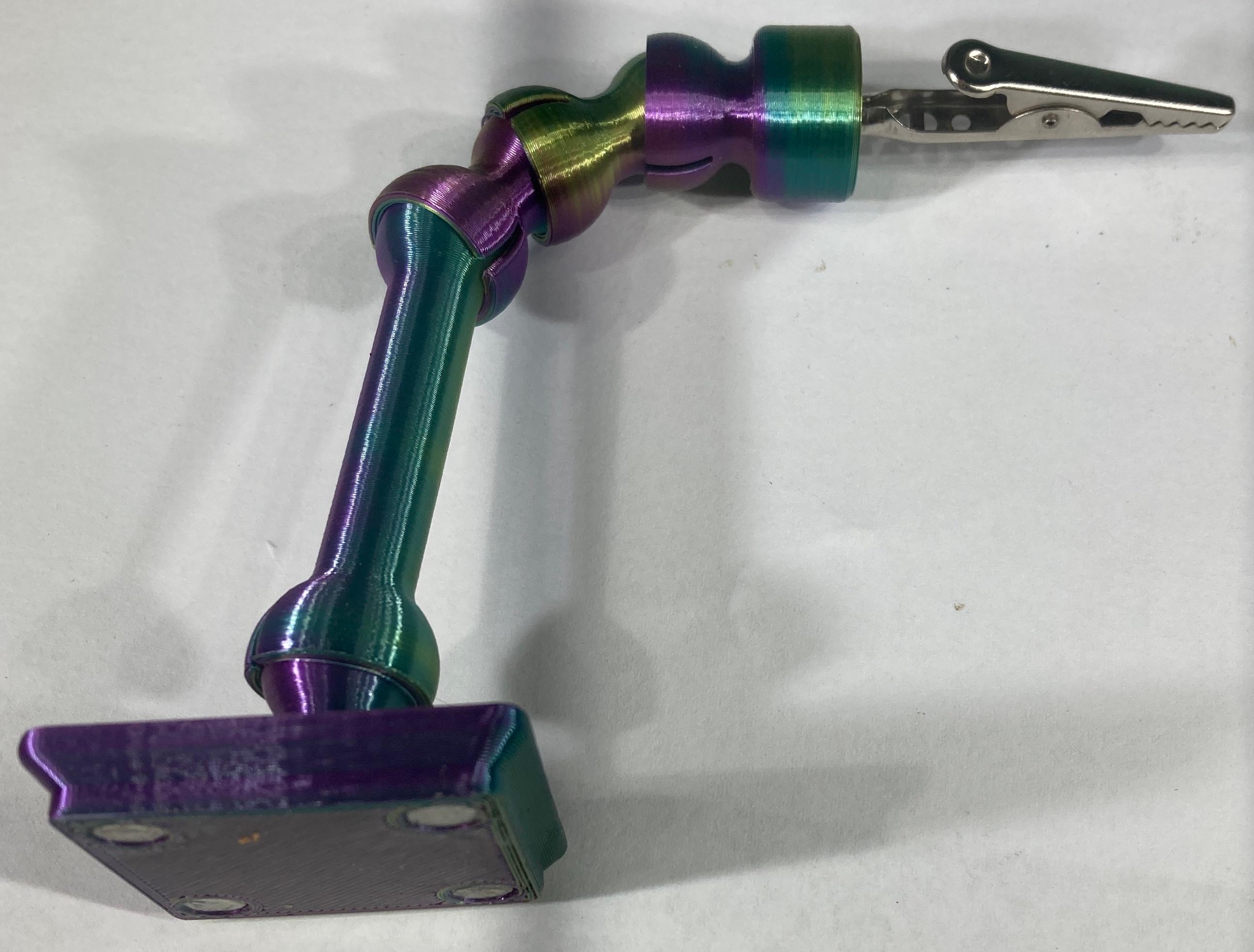
Tentacle System
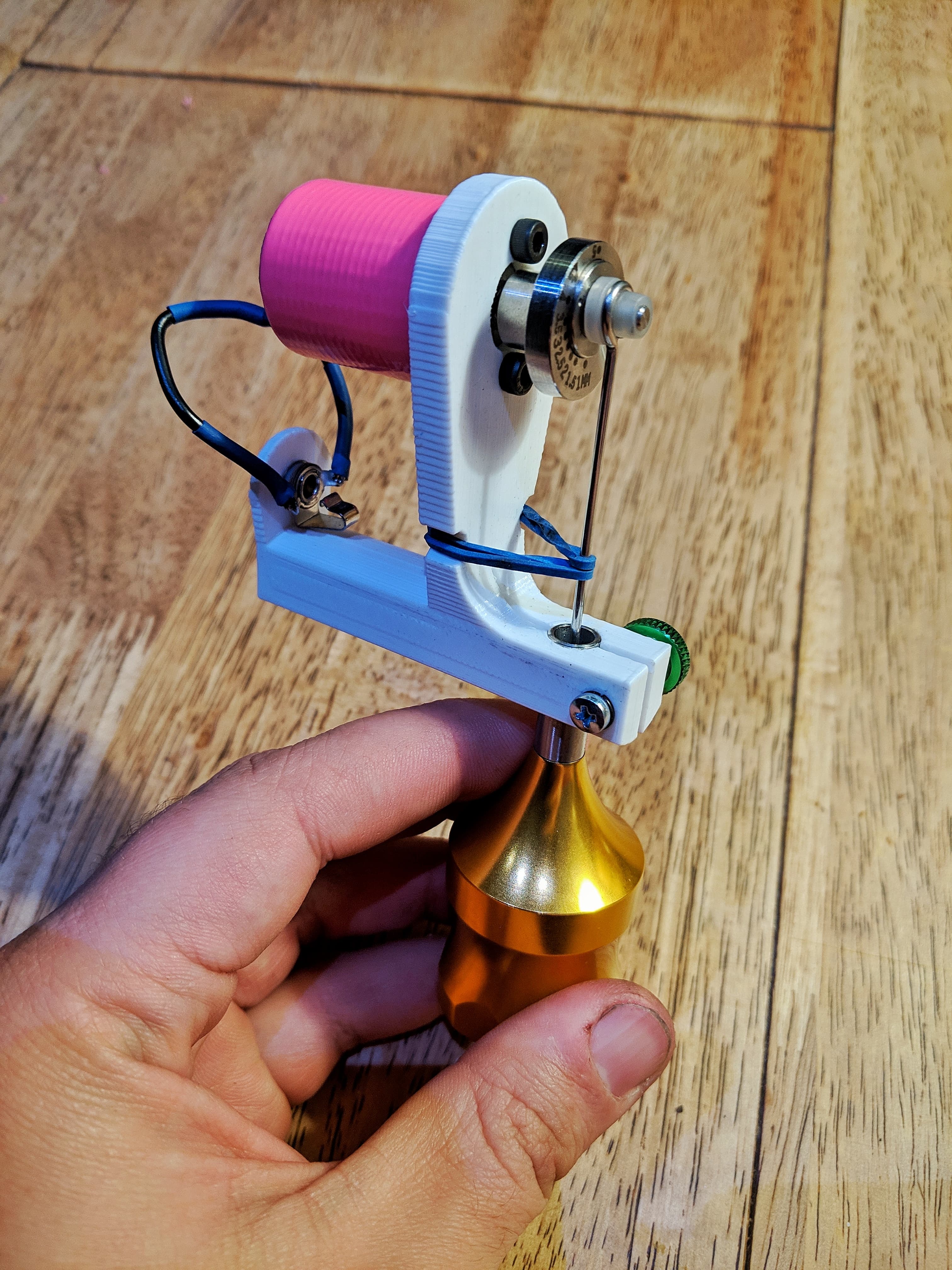
Rotary Tattoo Machine

Camera Matte Box for Vintage Lenses
#78 Wooden Vise | Fusion 360 | Pistacchio Graphic
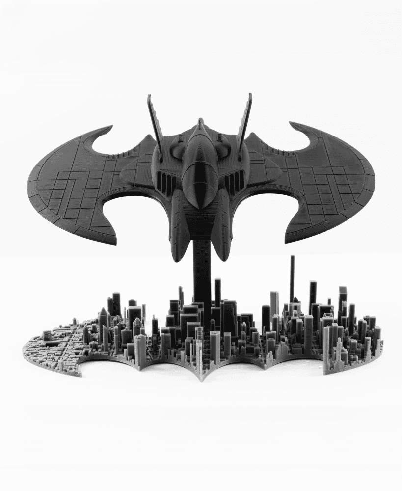
Batwing over Gotham City - Batman - DC - Fan Art - No Supports, No AMS
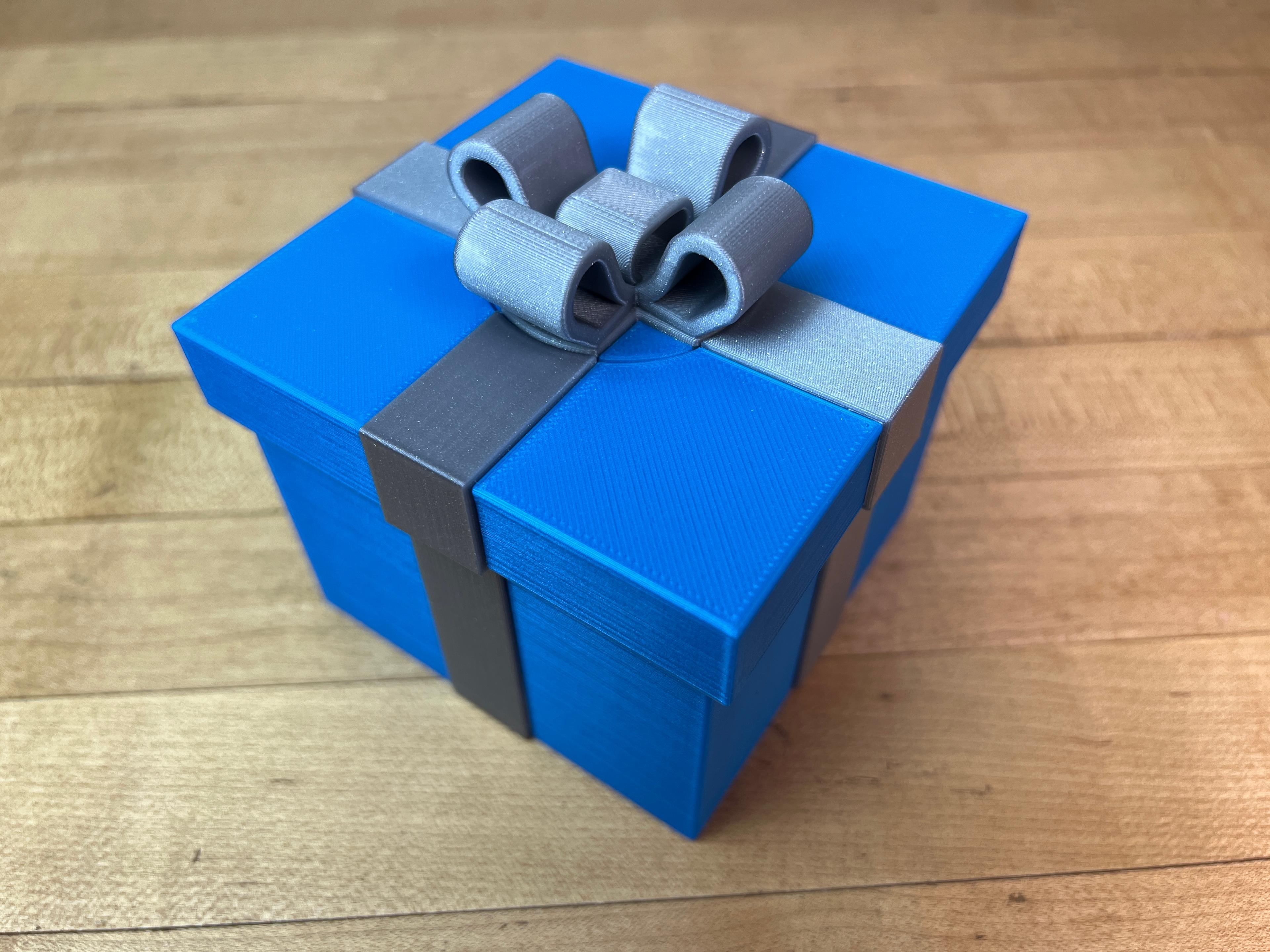
Gift Box #7

Cleo Lamp
Mini Print-in-Place Vise
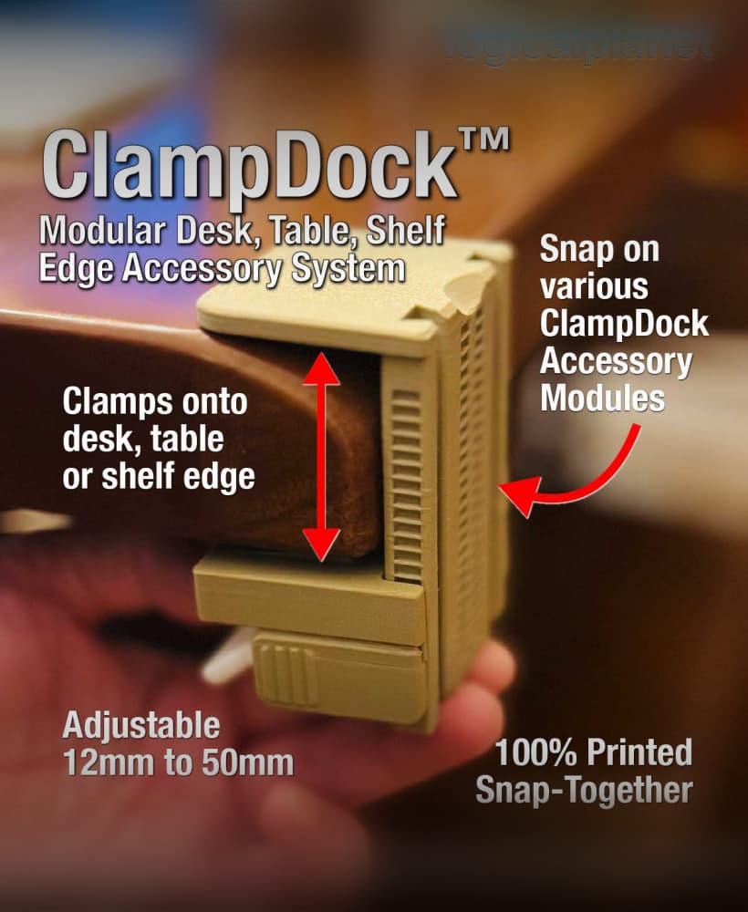
ClampDock (modular clamp-on system)