


Frame support for Tevo Tarantula
4 downloads · 3 years ago · Model originally uploaded to Thingiverse at https://www.thingiverse.com/thing:2656796.
<h2>Descript
This model is restricted by licensing terms.
View license.
Model originally uploaded to Thingiverse at https://www.thingiverse.com/thing:2656796.
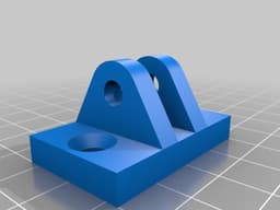
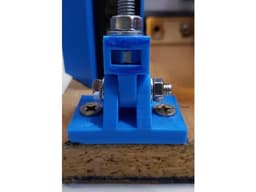
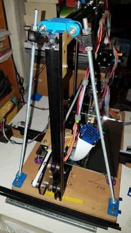
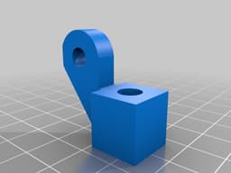
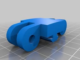
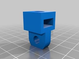
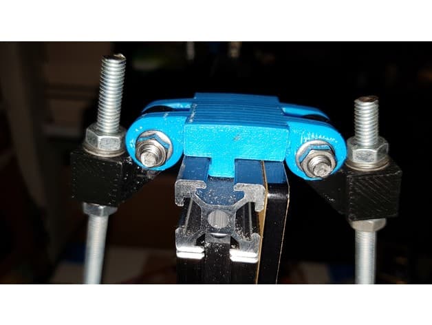
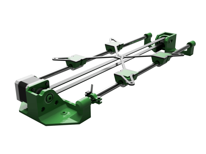
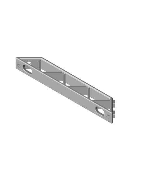
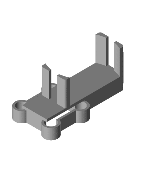
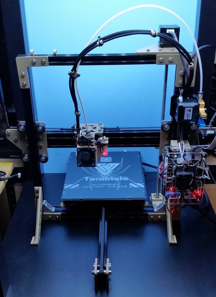
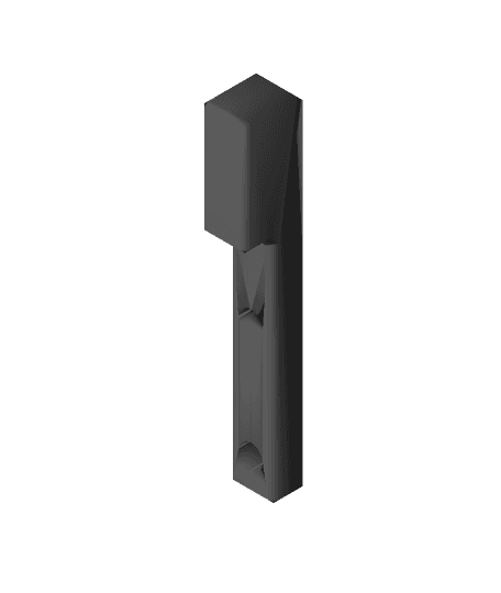
<h2>Description</h2> A frame support I designed for my Tarantula around the 6mm threaded rods I already had. <h2>Printed parts list</h2> 1 x Upper support 2 x Upper rod end 2 x Rod end 2 x Lower support <h2>Non printed parts list</h2> Threaded rods: 2 x M6x430mm. Can be longer but shorter will make the angles smaller and support not so rigid. Washers: 6 x Ø6; 8 x Ø5 Nuts: 8 x M6; 4 X M5 Bolts: 4 x M5x25mm <h2>Functional description</h2> I wanted to make my printer frame more rigid. So I mounted it to am MDF plate that I had and printed a bracket. But it looked wery weak after printing and I decided to make something stable. Found those threaded rods I had from before and desighed this using them as main piece for adjustment and stability. <h2>Printing tips</h2> Since those are structural parts print slower for beter filament adhesion. Should be printed in the orientations showed in the screenshot so the forces will be along the strands. Supports are needed only on those parts shown on the screenshot. <h2>Installation and adjustment</h2> 1) Install everything as shown in the photo. Dont tighten the nuts. 2) Tighten the upper nuts at lower rod ends to fix the screws\ 3) Adjust the frame to be perpendicular to the mount plate by tightening/loosening the top nuts at Upper rod ends. 4) Tighten counter nuts and transverse M5 bolts/nuts to fix everything. <h2>Others</h2> Designed in: eMachineShop Attached files: STL and EMS Material: used PLA(blue) but after some time Upper rod end delaminated so I redesigned it and reprinted in PETG(black).Frame support for Tevo Tarantula
4 downloads · 3 years ago in and
This model is restricted by licensing terms.
View license.
Frame support for Tevo Tarantula
Shipto you

HO Scale - (8) Dust Filter with Support Frames
Shipto you

N Scale - (8) Dust Filter with Support Frames
Tevo Tarantula Bed+Y-axis remake
Ender 5 S1 Back Frame Supports

HMG7.2 Tevo Tarantula Pro Gantry Adapter.stl

HMG7.2 Tevo Tarantula Pro Gantry Clip.stl

Fossil Pokemon Frame - Support Free
Dial gauge clamp for Tevo Tarantula
Riser for Tevo Tarantula Board to clear BLTOUCH

tevo_tarantula_pro_platform.3mf
Tevo Tarantula X-axis rebuild

tevo_tarantula_pro_platform.3mf

tevo_tarantula_pro_platform.3mf

tevo_tarantula_pro_platform.3mf
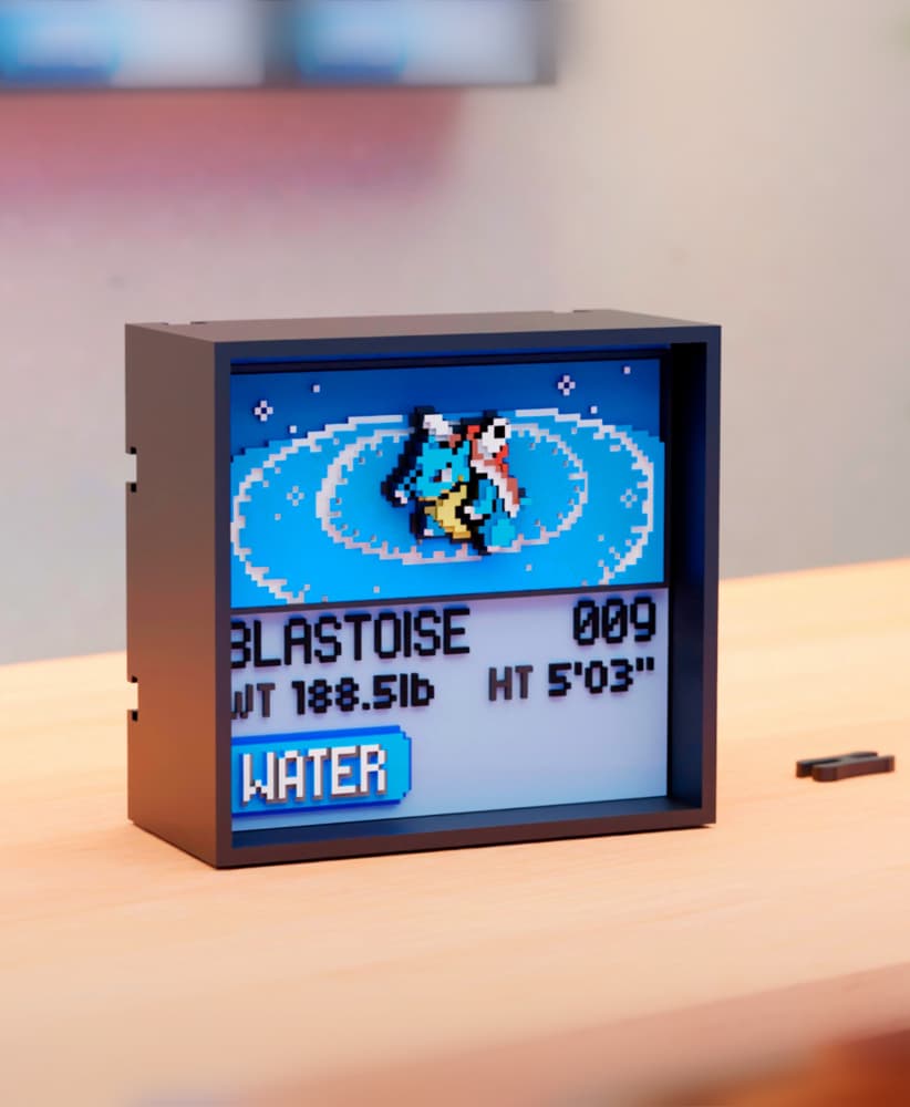
#009 Blastoise - Pixel Voxel Art Frame (No support, 3MF included)

#014 Kakuna - Pixel Voxel Art Frame (No support, 3MF included)
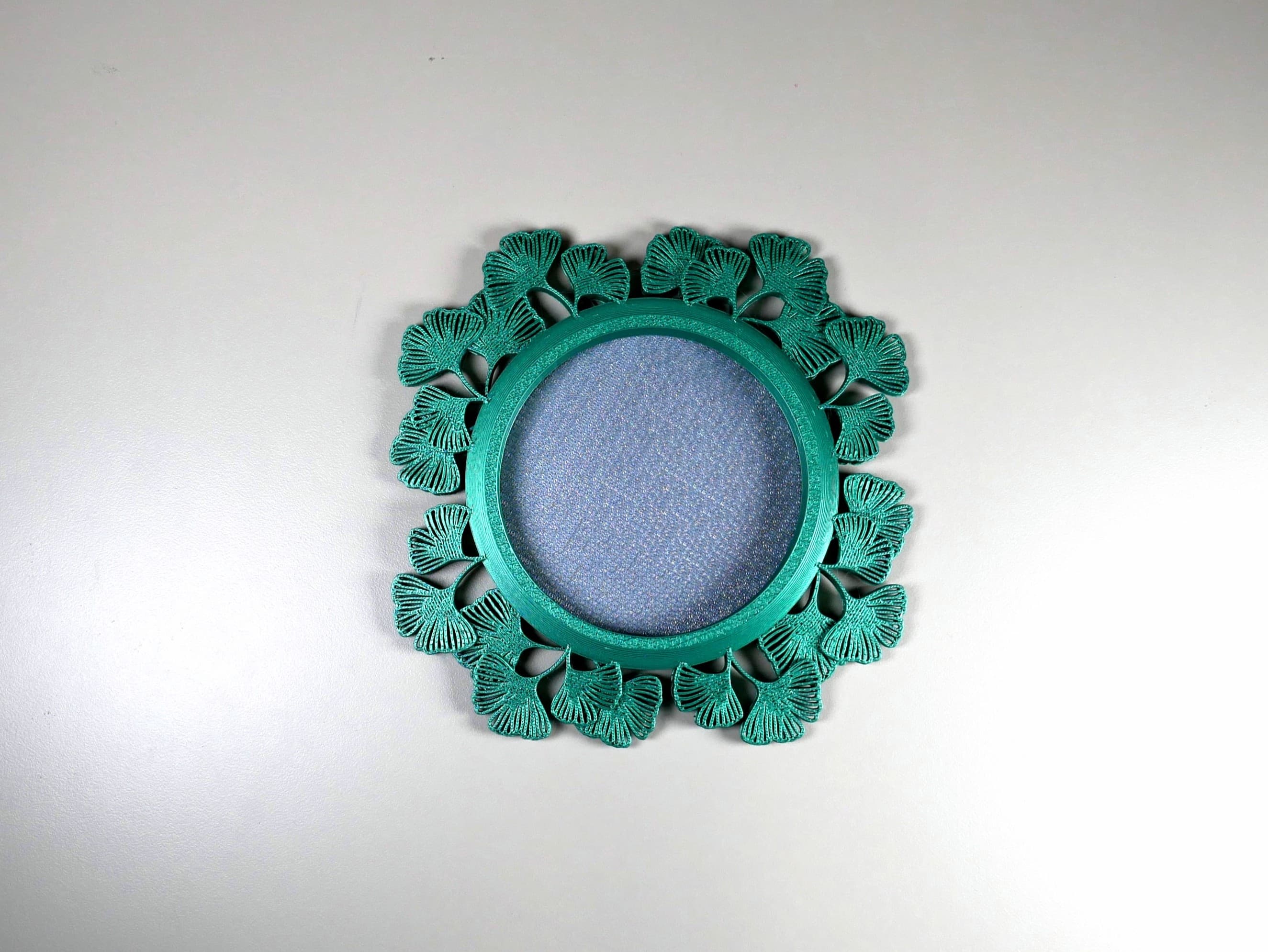
Ginkgo Picture Frame (No Supports)

#050 Diglett - Pixel Voxel Art Frame (No support, 3MF included)
