


Mastermind style safe unlock box
Model originally uploaded to Thingiverse at https://www.thingiverse.com/thing:3532363.
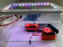
#Mastermind style safe unlock box This project turns a ikea perspex display box into a lockable and unlockable display case using a Arduino MKR NB1500 board for connectivity. The idea behind the safe is to open/unlock when a user gets the right code via SMS as part of a mastermind style game.
Connectivity in this build happens via the NB1500 which is catm1/narrowband enabled but a wifi board could just as easily be used.
Both the server side code and the arduino sketch run via a MQTT broker (Mosquitto)
<a data-flickr-embed="true" href="https://www.flickr.com/photos/developersteve/33735256078/in/dateposted-public/" title="AWS Summit 2019 - Telstra booth demo"><img src="https://live.staticflickr.com/31337/33735256078_a3b33f9a84_z.jpg" width="568" height="320" alt="AWS Summit 2019 - Telstra booth demo"></a><script async src="//embedr.flickr.com/assets/client-code.js" charset="utf-8"></script>
##Parts
- Ikea BJÖRNARP https://www.ikea.com/au/en/catalog/products/70364351/
- Full sized servo, (i used a AR-3606HB)
- LED strip (optional), just adds a nice effect and helps highlight the case.
- Mobile battery (i used a 10000mah dual usb power pack, ideally it needs to have 2 usb ports and support 5v out).
- USB cables, these are used to power the LED's and the Arduino on 2 seperate power lines (so long as theres 2 usb ports available).
- Spare wires (to solder the LEDs).
- Epoxy (to glue all the bits into the box
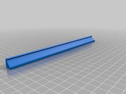
##Instructions Print out all the parts including 2x of each LED strip, this project can be built without using the LEDs but it does add a nice effect to the box and can be used to highlight when someone wins.
All the prints i printed at 20% infill and 0.25 height with supports on the things that need it.
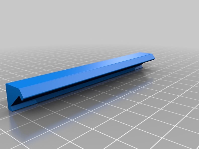
Solder strips of LEDs together making sure of the direction of the LEDs and that you cover the LED strip prints from above. Splice an old USB end to the end of the LED strip (power only!), you'll only need power and negative lines from the USB as the data line needs to run to the arduino (it controls the lights).
Glue the LEDs to the LED prints using small amounts of epoxy (usually the sticky backing on the strips isnt enough to hold them). Once the LED strips and LEDs dry glue into the top edges inside the box making sure the USB end fits into one of the back corners (to keep it out of the way).
The rack and pinion style gearing can be a bit tricky to lineup, basically the rack print from above needs to stick to the door and the servo with gear needs to mesh into it. In my build i cut a small hole at the side of the box so that the rack can slide the door open with the rack running through the hole at the side.
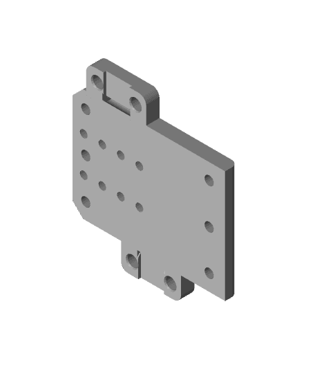
Screw the servo into the servo print above, in this build i used a AR-3606HB from Core Electronics (https://core-electronics.com.au/power-hd-continuous-rotation-servo-ar-3606hb.html). I also used the rubber stoppers from the servo to try and reduce vibration (and noise).
Once the hole is cut in the side of the box and servo screwed in and ready to go, carefully glue the rack onto the door so it slides through the side. Once dry glue the servo to the bottom front of the box so that the gear will mesh into the rack glued onto the sliding door.
Plug the LEDs data line into the pin you want to control the LED strips from, Plug the servo into the iot board you used. The servo i used in this build needs 5v so is powered from the 5v pin on the NB1500 with a data line running to a pin on the board.
For those using a Arduino MKR NB1500 i've also designed a case for it, see https://www.thingiverse.com/thing:3460266
When everything is glued, dried and assembled load the server side code and the sketch to the arduino or IOT device you used. Plug the USB for the LEDs into the battery and power the arduino. For the arduino i just powered this build from the same battery the LEDs run from and the servo running its power from the Arduino. This can be changed around depending on your build requirements.
I wont go into the code side of things but the full code for server side and device side can be found here https://github.com/telstra/AWS-Summit-2019-Demo-Game. The game itself (written in Python) puts a message into a broker queue that the device then receives and triggers the door to open.
Mastermind style safe unlock box

Ammo Box Container — Military Style Storage Box
Magnet Box with Tackle Box Style Hinge

Packout Style top containers for Milwaukee Style packout boxes.

Happy Birthday Cookie & Clay Cutter, Gift Box Style Design, Cookie Biscuit Stamp, Fondant Cake Decor
Box Style Check (Key Lock)
Titanic Movie Safe Box
HMG7.3 Voron Style Box X Carriage 5015 Fan Standard Duct.stl
HMG7.3 Voron Style Box X Carriage 5015 Fan Tall Duct.stl
HMG7.3 Ender 3 Style Box X Carriage Front.stl
HMG7.3 Ender 5 Style Box X Carriage Front.stl
HMG7.3 Ender 3 Style Box X Carriage Bottom.stl
HMG7.3 HyperCube-BLV Style Box X Carriage Tall Back.stl
HMG7.3 Mercury One Style Box X Carriage Short Back.stl
HMG7.3 Mercury One Style Box X Carriage Front.stl
HMG7.3 Voron Style Box X Carriage Bottom.stl
HMG7.3 Voron Style Box X Carriage Tall Back.stl
HMG7.3 HyperCube-BLV Style Box X Carriage Front.stl
HMG7.3 Voron Style Box X Carriage 5mm Flush Belt Clips.stl
HMG7.3 Voron Style Box X Carriage Front.stl