


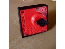


Picoscope- DIY SmartPhone Oscilloscope using Raspberry Pi Pico
Model originally uploaded to Thingiverse at https://www.thingiverse.com/thing:6017606.
Sometimes when you repair some electronics hardware and do some Research and Development work, you need an Oscilloscope. You can use multimeters as well, but the problem with multimeters is that they aren’t fast enough to detect the signals. There is a standard oscilloscope for lab and industrial applications.
When you go through the pricing of a commercial oscilloscope, you will realize it is not affordable for beginners. If you are an electronics hobbyist or some technician and if you are unable to buy these, then here is a solution for you. We can design a simple DIY SmartPhone Oscilloscope using a microcontroller at a very low price probably at 5$ only.
Read further from https://how2electronics.com/diy-smartphone-oscilloscope-using-raspberry-pi-pico/
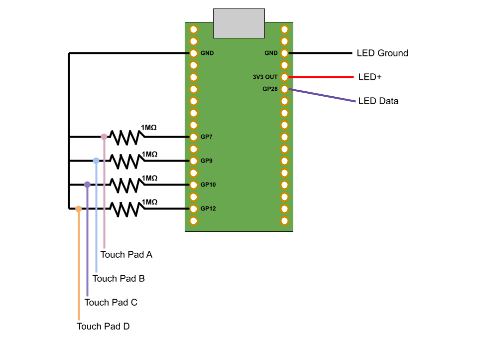
This model uses the rotary switch circuit to shift between voltage dividers to make it feasible for the pico to measure safely. Circuit diagram- https://how2electronics.com/wp-content/uploads/2022/02/DIY-SmartPhone-Oscilloscope-1-580x439.jpg
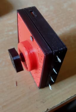
The rotary switch is taken from an old ceiling fan speed regulator. This has 5 steps. The resistors i have used in series are 100k,100k,10k,1k.
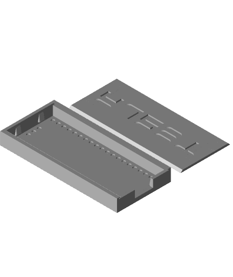
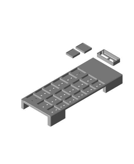
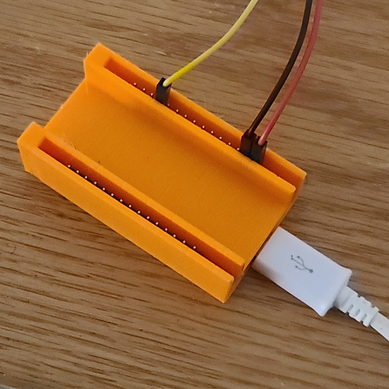
You may need to give support for printing the top cover.
Please use aligator clips to connect the testing device.
Picoscope- DIY SmartPhone Oscilloscope using Raspberry Pi Pico

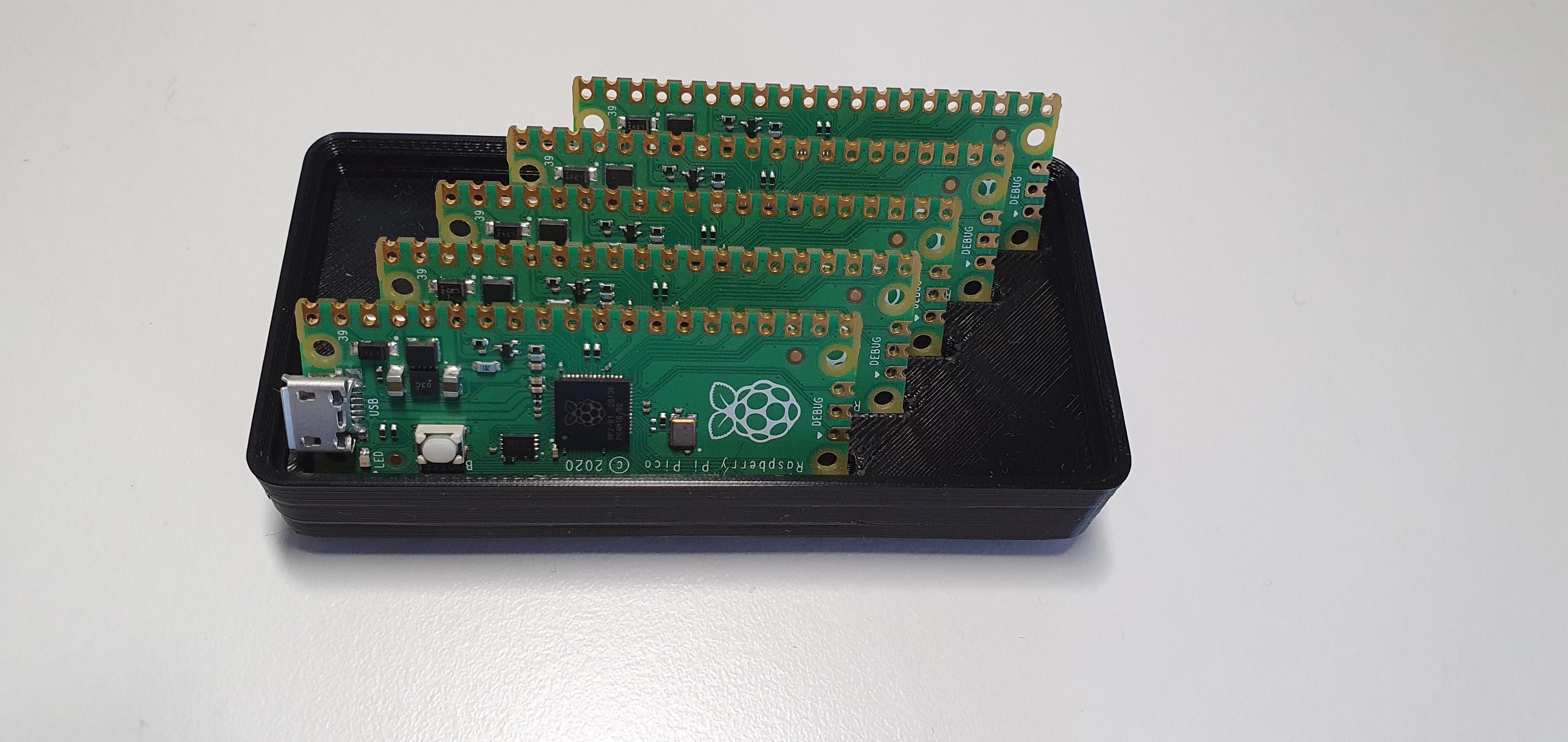
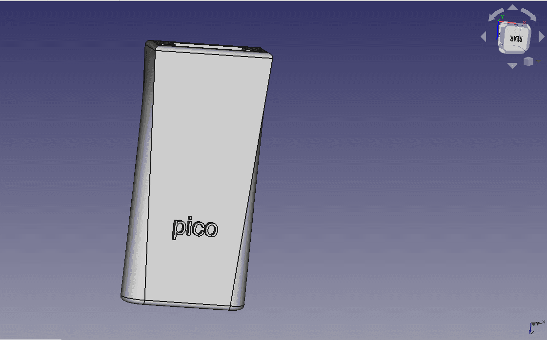
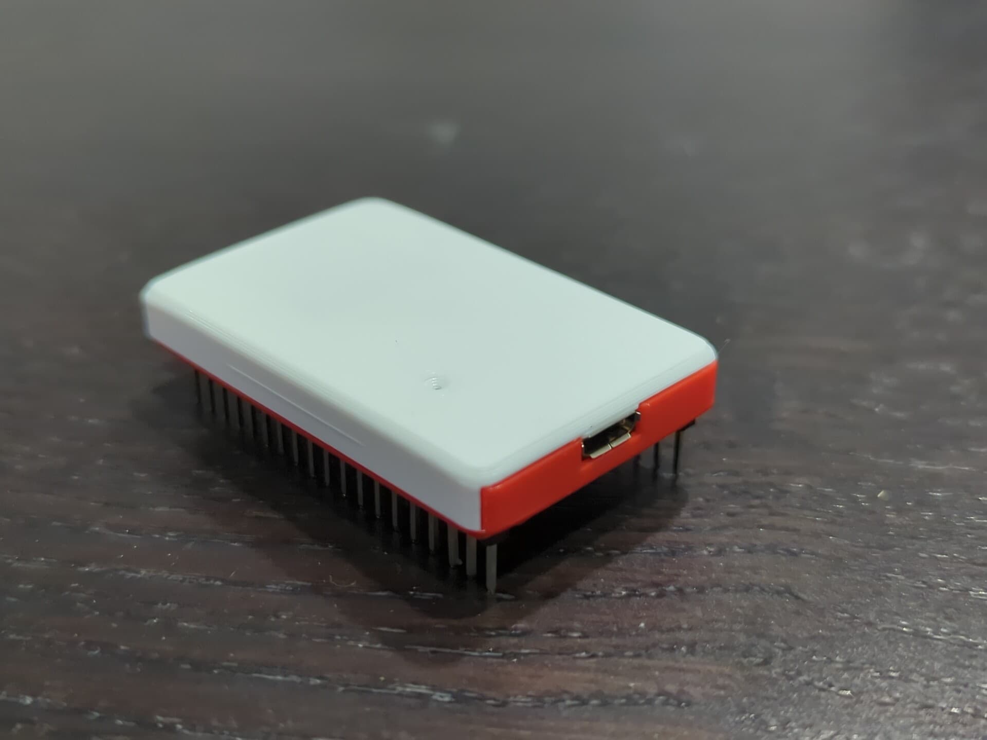
M!N!MAL Pico - A Raspberry Pi Pico Case

Raspberry Pi & BigTreeTech Pico 40mm Fan Mount - Pi Zero 2W 3 4
Gridfinity Raspberry Pi Pico Holder.stl
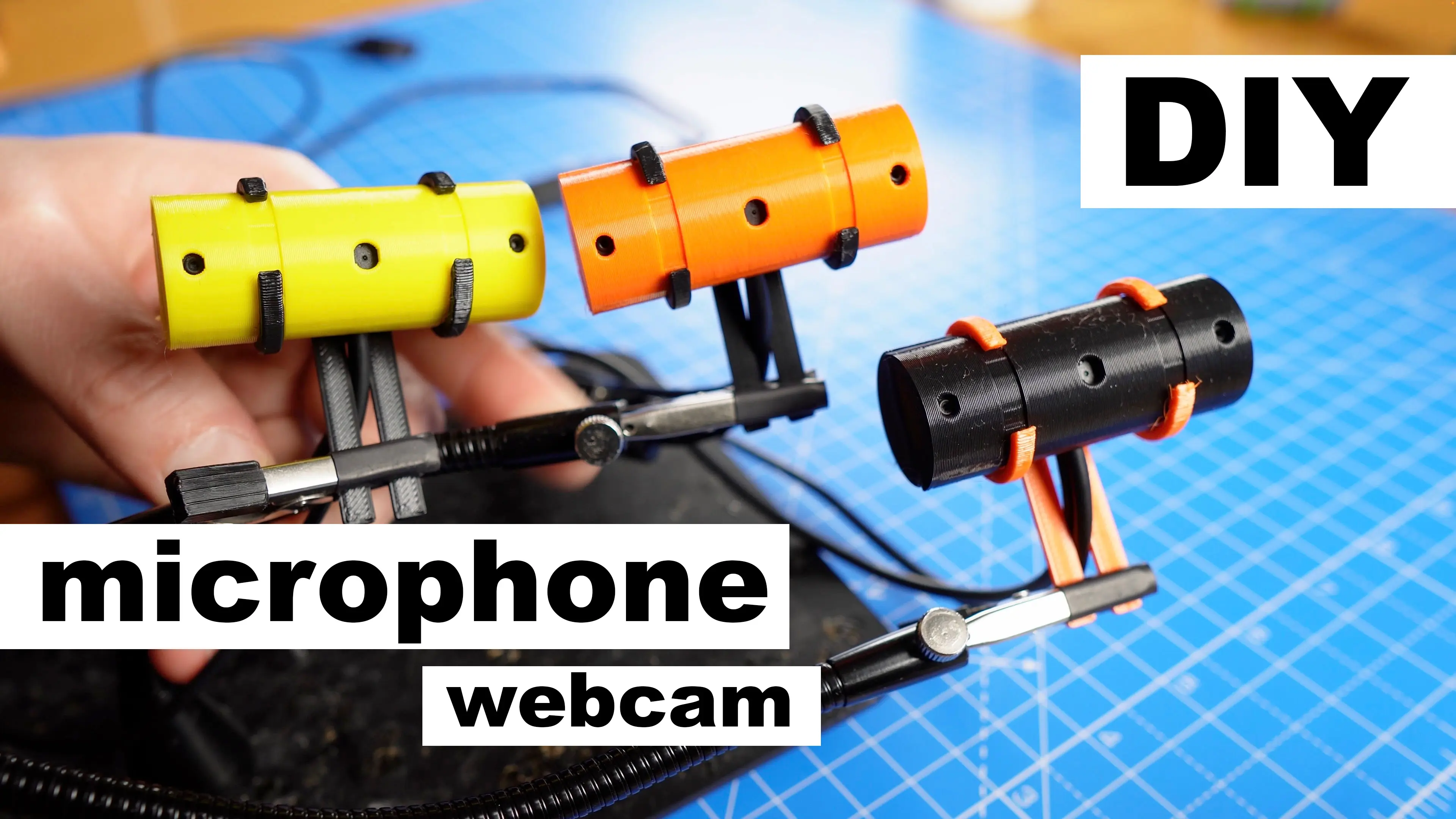
DIY usb microphone and camera from old laptop with Raspberry Pi Pico
Raspberry pi pico case with tesla logo
Raspberry Pi Pico Case used as "Rubber Ducky Bad USB"
Raspberry Pi Pico snap-together case with slot for 6-wire ribbon cable
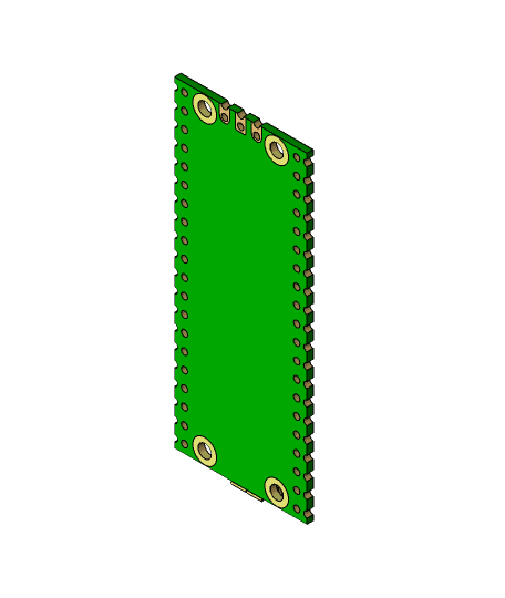
Raspberry Pi Pico
.png&w=3840&q=75)
Interactive Under Screen Pi Pico Setup
The Block Swapper
BTT Pico Board Mount for Voron V0.1
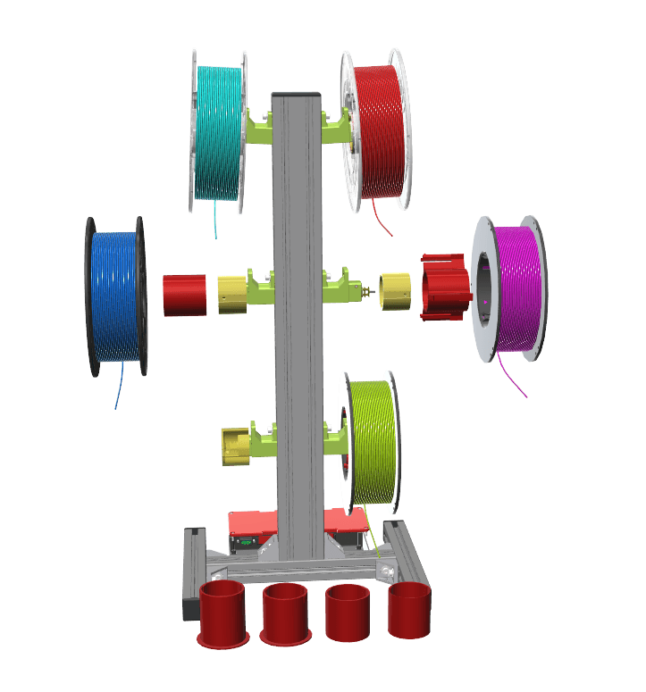
Motorized Spool Rewinder (SMuFF)
Slim case for ESP32 Devkit V4

Weyland Yutani CyberDeck

Ghost Trap
MCU Guard! The rapid enclosure for microcontrollers!
roLED Addressable RGB Wristband #hallowearable #hallowearables

DIY Traffic Light
NodeMcu V3 Base.stl
