Model originally uploaded to Thingiverse at https://www.thingiverse.com/thing:2809935.
This is Marlin 1.0.0 5th March 2018 Update, changed stepper motor current to 1200ma after more testing as homing z axis was proving to be a bit random where it homed.
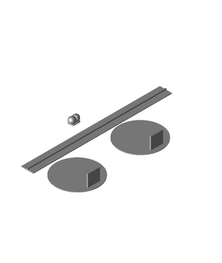
Bonus! Pringles packaging to hold objects inside Pringles tube, just glue the lip on the disc's to the long part and the little handle to pull it out if you like.
Due to my brand new Tronxy X5S having a faulty mosfet on the extruder, which means it never turns off (Not good) I'm trying t get the supplier to send me a replacement board.
But I want to use it now! And I had a Ramps 1.4 I bought about a year or so ago just sitting in a box, so..............
Disclaimer! This is a work in progress, and not fully functional, but close enough to get good prints (PLA tested) I tried to find a way to use a Ramps board to do this, but many clickbait links later, I decided to have a go myself. I'm not an expert by any means in configuring firmware etc so please bear that in mind, it's just me releasing what works for me in case someone else need help. The original X5S firmware setting have been used where possible. Please bear in mind this is just the work of a couple of evenings and will no doubt need some clarification in places.
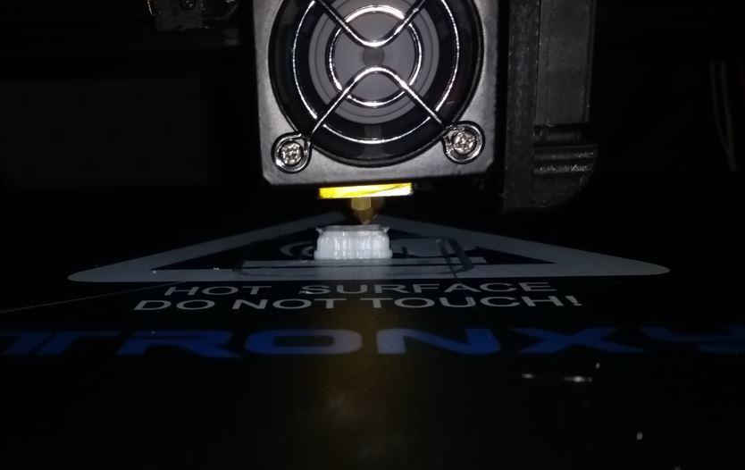
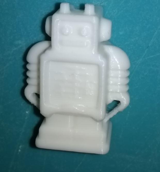
The Makerbot pic was printed on my converted printer and is shown being printed too, it looks pretty good to me, but maybe white doesn't really show very well in the photo.
Ok, what works and what doesn't
All of the stepper motors and hot end work fine.
The Heat bed, which is a biggie for the little Ramps board really needs an external mosfet to help it heat up, the transistors/mosfet's on this board were not made to run a heatbed this size, but I found if you keep the heat bed to 30 degrees it seems to cope Ok.
Hopefully the original LCD will work when I get a board to connect it up I've not tested it yet, but the problem might be that because this LCD unit has no sdcard reader built in, it may not be an ideal solution and you may have to use a different lcd unit and the firmware adjusted to suit..
The SD card reader also is enabled in the firmware but not present on mine yet so is untested.
So USB printing from Cura etc is working as far as I can tell.
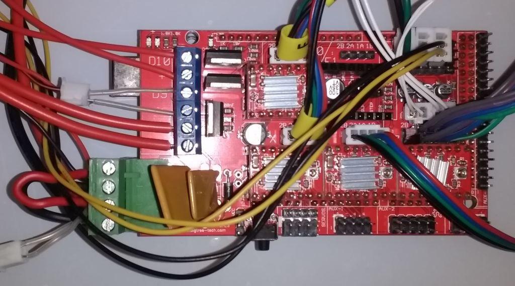
The Z axis steppers connect to two separate connectors but share a stepper driver, so you will need to increase the driver current using a small pozi or philips driver. The standard voltage measured on the driver is 560mv it needs adjusting to 1200mv or the z axis steppers will judder when moving up, you can try increasing in 200mv steps from the original 560mv, and test when homed to see if the steppers have any strength. Compare how powerful the x and y motors are after homing by lightly turning them, they should be reasonably hard to move, the z steppers should be similarly resistant to you turning them. The two z axis steppers are connected on the right hand side of the board, in my case I used male to female arduino patch cables about 20cm and plugged them straight (in the same order as the board pins) into the original z axis motor plugs in my case grey lilac blue green into black green blue red. They are just too close together to plug directly into the ramps board.
I'll try to add a link in here so show the adjustment process.
Ok, in the photo of my ramps board, you can see the original steppers are plugged directly into the dupont pins on the board. This works perfectly, you don't need to cut off the old plugs and solder or crimp on new ends, the same goes for the for the temperature sensors and endstops. Endstop warning!! Do not use the bottom row of pins in the endstop bank of pins, it's the power + pin row, you WILL blow up your arduino's 5v regulator and you won't be happy! My plugs are middle to top pin never the bottom pin!
The part cooling fan connects to the D9 The extruder body fan just connects to any 12v outlet you can find, (mine is wired to the 12 volt input) Use Arduino 1.0.6 to install the firmware and you should be good to go. Make sure you select your arduino model and com port. Extract the files There is a marlin.ino in there that you should select Then upload to your Ramps board and it should work, I'll test the sd card and lcd when I get the bits.
I would definitely recommend you add a cooling fan on this or the Ramps board may not last very long.
Please let me know if you spot any mistakes in the above. See below Youtube video for how to set stepper current.
Mine are clockwise to increase current
https://www.youtube.com/watch?v=XU6lgFeZ7ZQ&t=231s
See http://domoticx.com/arduino-mega-shield-ramps/
For connections