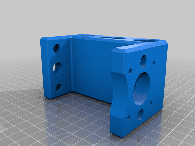
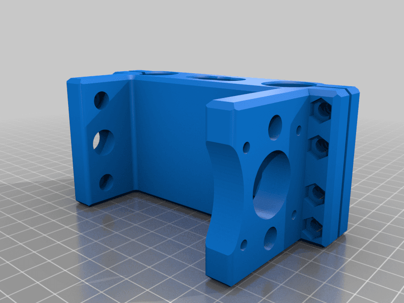
Model originally uploaded to Thingiverse at https://www.thingiverse.com/thing:4138858.
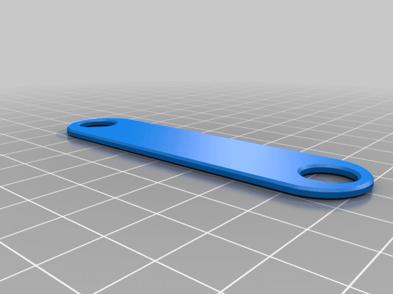
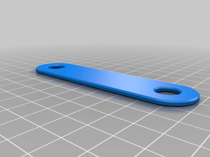
Important! Before printing this, please check the spacing of your CNC X axis rods. I've added two test pieces to check the fit before printing. One for 68mm spacing and one for 72mm spacing. I didn't realise there were so many variations in this design.
If you have the 72mm version, there are two versions, one of them has a recess on the right for the x axis lead screw coupler.
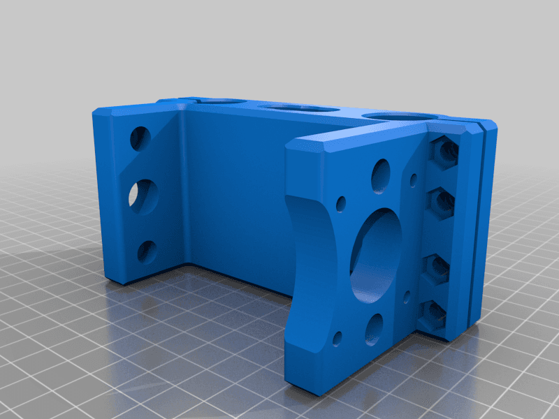
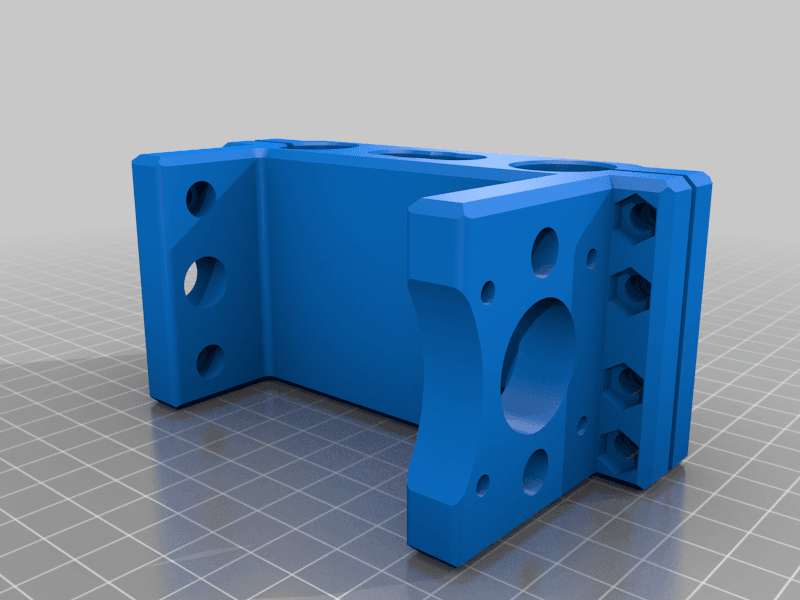
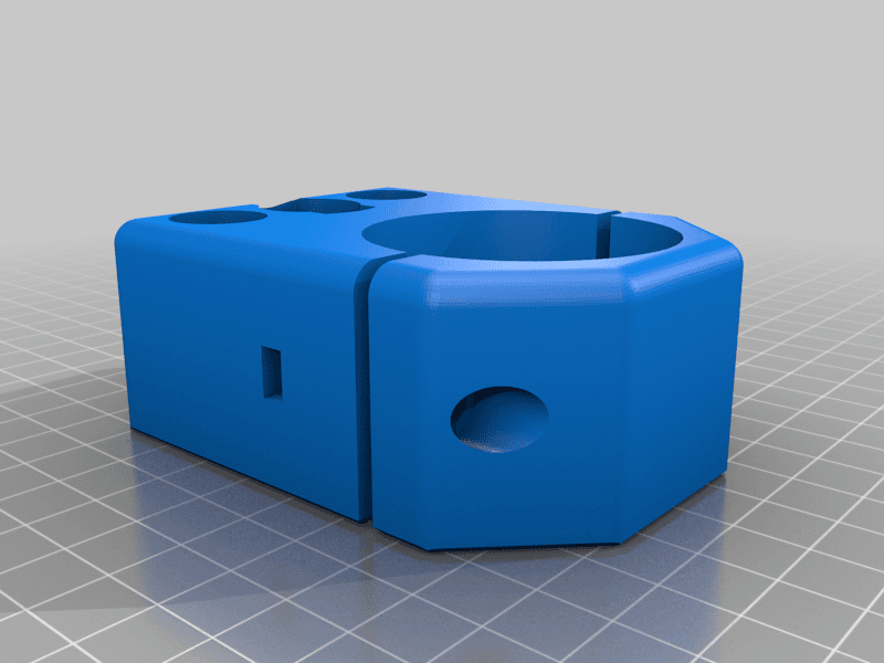
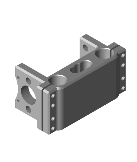
Another update!!* I finally got my new LM10uu linear bearings, and wow they are hard to fit, especially if you make the rear part almost solid. I had to saw a slit in the top and bottom of my first print to get enough room to press the bearings in place. So in an attempt to make it easier to assemble hopefully without compromising strength, I've added the v3 of the rear mount with clamps that takes 8 x 20mm m5 bolts to lock the bearings in place. (don't over tighten, the bearings seem to get notchy/rough if squeezed too tight, but that might be my imagination!) I would suggest that this is the version you print, I used 7 walls (3mm) and 60% infil (very solid) and zero slop in any axis :)
I haven't included step files of this version.
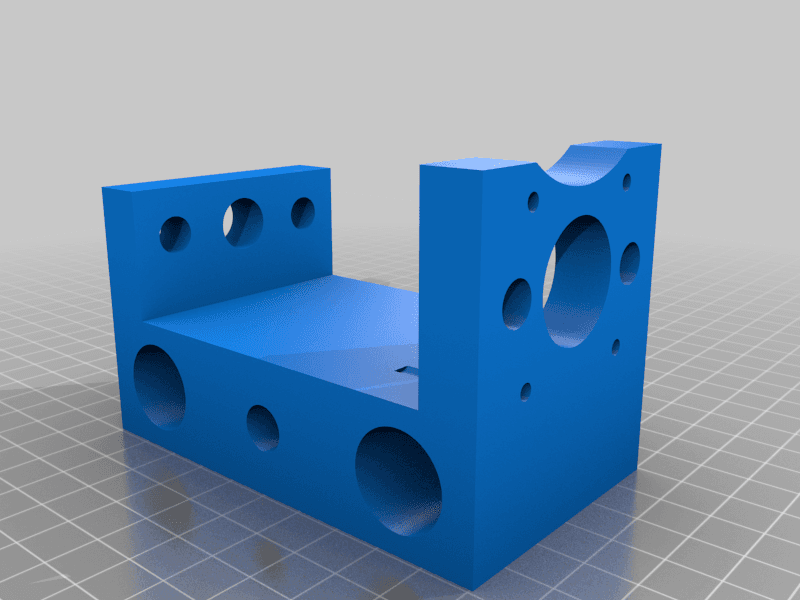
Update! The Rear mount was missing the cutout to allow the spindle motor to clear stepper mount when raising or lowering. Now fixed.
Originally my cnc mount cracked at the clamping screw, so I took it apart to make a replacement part, however it all went bad from there.
The linear bearings in mine were either bad/sloppy or something, so taking it apart just made things impossible to just swap. There were weird thing like the two 8mm z axis rods were different sizes, one was 7.99 the other 8..05 and was extremely tight.. The lm10uu's in the main carriage were just really sloppy.
And when I took the main carriage part off, that was cracked too.
I've ordered some spare rods and bearings but I've made some replacement parts.
I've uploaded step parts too in case anyone want's them.
I hope all of the dimensions are correct, just let me know if not..
I'll also mention that my spindle motor has a metal band around it (which most seem to have) making it 45mm diameter
