PowerSpec Ultra SKR Upgrade
Model originally uploaded to Thingiverse at https://www.thingiverse.com/thing:4293904.
I'm upgrading my PowerSpec Ultra 3D to get rid of the proprietary board and to upgrade to silent stepper drivers. The stock, closed-source firmware is also missing a lot of features like basic PWM fan control, z-offset, PID tuning, etc. And the WiFi board stops working if you update to the latest FlashForge Dreamer firmware. This may work with other FlashForge Dreamer clones from Qidi, CTC, Dremel, Wanhao, etc. with modification. I'm not sure if anything will fit the newer PowerSpec Ultra 2.0 3D printer.
<h1>Parts:</h1> <i>(affiliate links)</i> <ul> <li>SKR 1.3 board and 5x TMC2208 drivers: <a href=https://amzn.to/34Ujtcq>https://amzn.to/34Ujtcq</a></li> <li>or SKR 1.4 board and 4x TMC2208 drivers: <a href=https://amzn.to/3cV4GRG>https://amzn.to/3cV4GRG</a></li> <li>2x M3 Thermistors: <a href=https://amzn.to/2XXr7l6>https://amzn.to/2XXr7l6</a></li> <li>2x MK10 heater blocks: <a href=https://amzn.to/3cDMeN9>https://amzn.to/3cDMeN9</a></li> <li>10 pack JST 2-pin connectors: <a href=https://amzn.to/2zJELhn>https://amzn.to/2zJELhn</a></li> <li>2 pack LM2596 buck converter: <a href=https://amzn.to/3daVhFP>https://amzn.to/3daVhFP</a></li> <li>4 channel relay board: <a href=https://amzn.to/3d3ncHF>https://amzn.to/3d3ncHF</a></li> <li>MOSFET: <a href=https://amzn.to/2NkYc3L>https://amzn.to/2NkYc3L</a> (optional, in case you want to use another 24V power supply instead of upgrading, 2 pack, only need 1)</li> </ul>Edit: switched to a SKR 1.4 Turbo because it was only $1 more than the 1.3 (but with 4 drivers instead of 5).
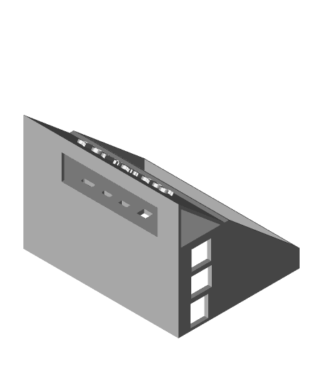
<h1>LCD:</h1> Switched from the color touchscreen from the original Ultra to a 12864 LCD from an Ender 3. Note that other 12864 LCD boards may have a slightly different layout. I had to drill a hole in the Ultra's case for the encoder shaft to fit through.I included two files: "12864 LCD for PowerSpec flush.stl" for the screen fitting flush against the case and "12864 LCD for PowerSpec inset.stl" where the screen is 4mm inset from the case because I found that the encoder stuck out on the PCB too much. I would recommend printing the inset one for the PowerSpec Ultra 3D and use the flush model if you want to modify it for other 3D printers.
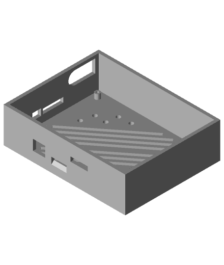
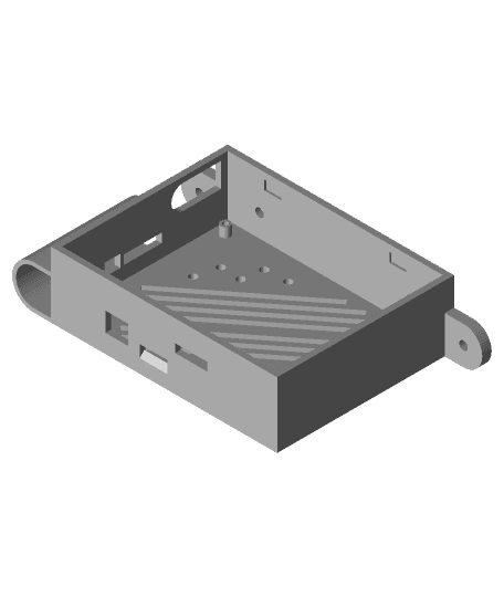
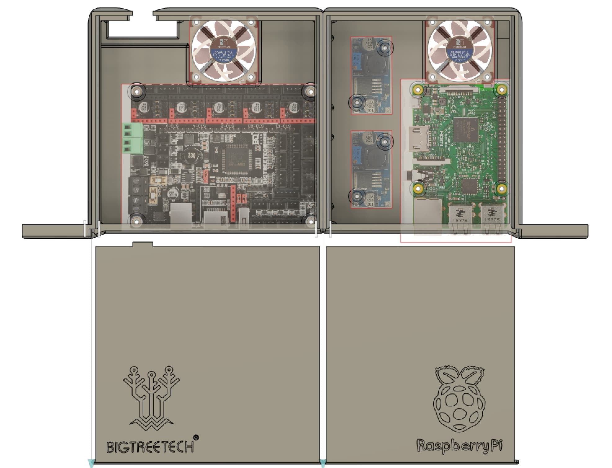
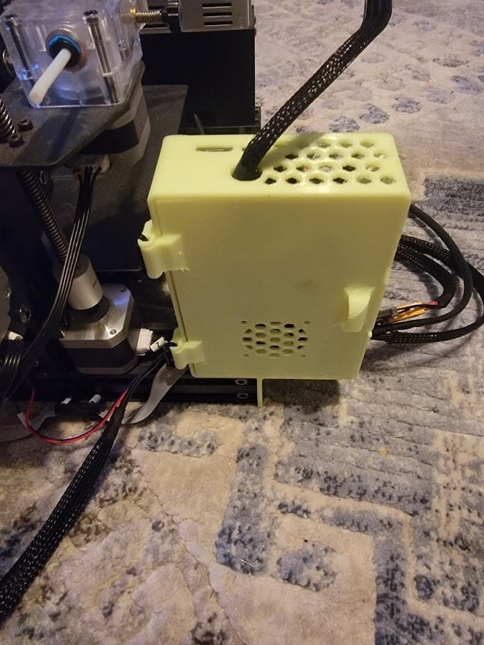
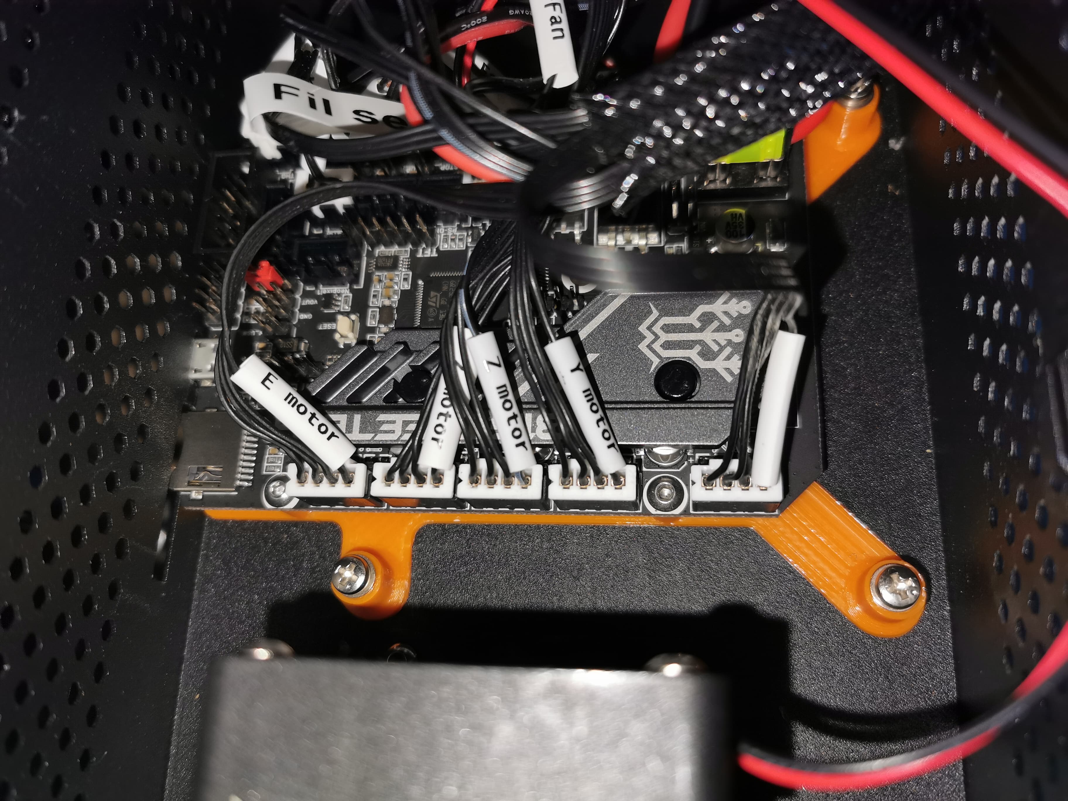
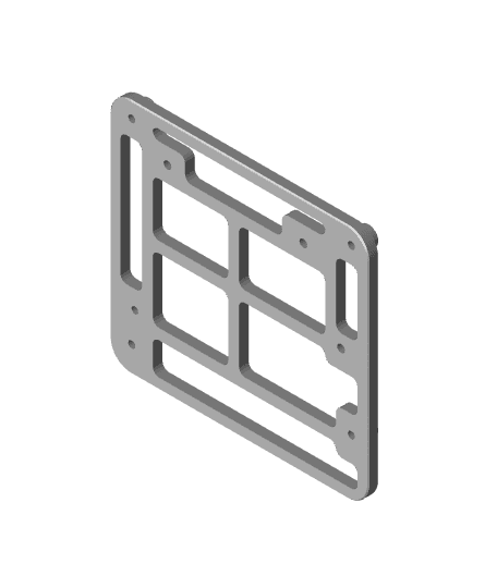
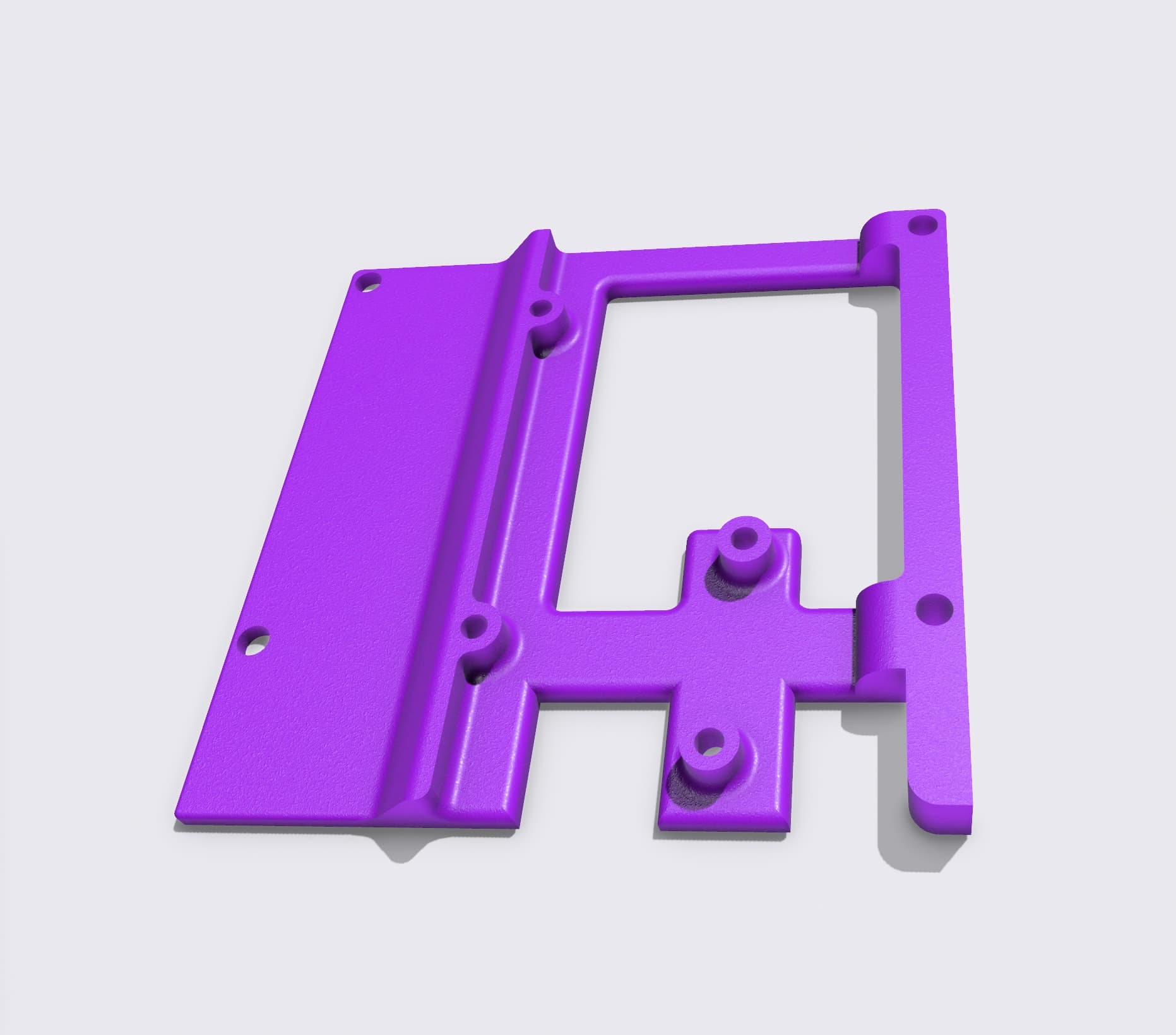
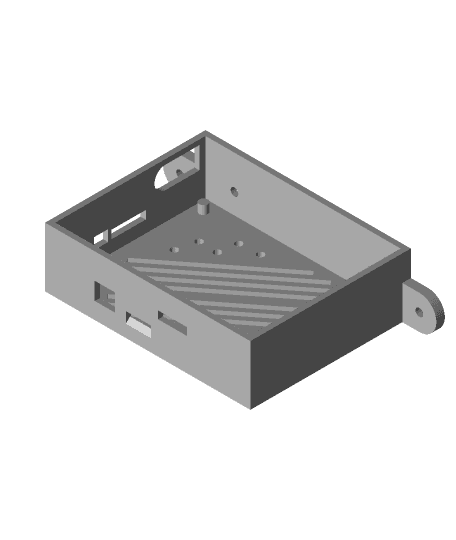
<h1>Motherboard:</h1> Switched from the FlashForge DriverBoard Rev F to a SKR 1.3. Print out four "PowerSpec_Ultra_to_SKR_StandOffs.stl" and use the original M3 screws to screw the printed adapter to the original standoffs. I put some electrical tape on the head to make sure it doesn't short anything on the bottom of the SKR. Then secure the SKR to the new wider standoffs. This should also fit other MKS Gen L and some SKR boards that use 101.85 mm x 76.10 mounting holes. I recommend screwing in the screws before you install it in order to make the threads. <h1>Pi/Relays/Buck converter</h1> I added a file "PowerSpec_Ultra_pi_mount.stl" which mounts to the existing standoffs that were used for the CoreBoard. It allows you to mount a Raspberry Pi (tested with a 3B), LM2596 buck converter, and 4 channel relay board <strike>(currently not tested, but I will update when it arrives)</strike>. The bracket lets the Pi's network port sit flush against the cutout for the USB Type-B port. The Pi's USB ports are blocked, but I use the GPIO pins on the Pi to connect to the SKR board, and I wired the buck converter to the test pads on the bottom of the Pi for power. You can cut out the side of the case with a Dremel or just use the bracket as a reference for your own design if you need access to all of the ports on the Pi.Edit: added "PowerSpec_Ultra_pi_mount_v2.stl" which should fit the 4 channel relay properly (65mm x 45mm mounting holes). I also added "5mm_Standoff_for_Relay_Module.stl" to lift the relay board away from the screws that hold in the bracket.
<h1>Hardware things to note:</h1> <ul><li>Had to change from thermocouples to thermistors (which mandated different heater blocks as well, since FlashForge uses M4 threads for the thermocouple instead of M3 that most thermistors use). <strike>Someone mentioned that you could use the M3 thermistor instead of the grub screw on the stock heater block, but that seemed like a bad idea.</strike> Edit: the grub screw is M4 and on the bottom of the block, so it wouldn't work anyway. (unless they meant the M4 grubs screw above the heater block that holds in the throat which would probably be too inaccurate).</li> <li>With the above heater blocks that I ordered, I had to widen the hole for the heater cartridge with a 1/4" drill bit, the original diameter was slightly too small. They're also not mirrored, so one had to be upside down, so make sure to screw in the grub screw for the one that would be blocked by the cooling bar assembly.</li> <li>I also found this M4 thermistor connector that you might be able to use if you don't want to change the heater blocks and if you have a thermistor that fits in it: <a href=https://www.ebay.com/itm/M3-M4-Thermistor-Hot-End-Screw-Type-Thermistors-For-3D-Printe/392200661436>https://www.ebay.com/itm/M3-M4-Thermistor-Hot-End-Screw-Type-Thermistors-For-3D-Printe/392200661436</a></li> <li>The heated bed thermistor wiring is white (signal), green (ground), yellow (ground), blue (5V) and is just a standard 100K thermistor, so I just used white/green.</li> <li>The end-stops are red, black, green, black, but I just used red/black for signal/ground.</li> <li>EX1/EX2 on the FlashForge board are green (ground), orange (24V), black (ground), red (24V) - green/orange are for the heater cartridge and the red/black are for the hotend fan</li> <li>The motherboard cooling fan's positive/negative on the 2-pin JST were wired backwards from what the SKR uses. The same goes for the orange/green JST connector for the part cooling fan. I would recommend buying a pack of 2-pin JST connectors to use with the fans and end-stops.</li> <li>I had to set MAX_BED_POWER 215 in Marlin otherwise bed heating would fail. Apparently this is due to the printer's underpowered PSU/low resistance bed, and it is recommended to upgrade to a 450W or higher. Edit: I ended up just using a spare 350W 24V power supply and a MOSFET. Previously, heating would fail if I tried to heat the extruder and bed at the same time, and the bed would struggle to get higher than 60C. Not sure how the stock firmware manages to do it, since I used to be able to do 100C without any issue.</li> <li>I inverted the direction on the right extruder in Marlin. Also, I had previously swapped the red/yellow wires on the stepper motors on X/Y/Z to invert their direction using hardware instead of software (when I just used the stock board and TMC2208s in standalone mode), so you might have to invert these in software.</li> </ul>PowerSpec Ultra SKR Upgrade
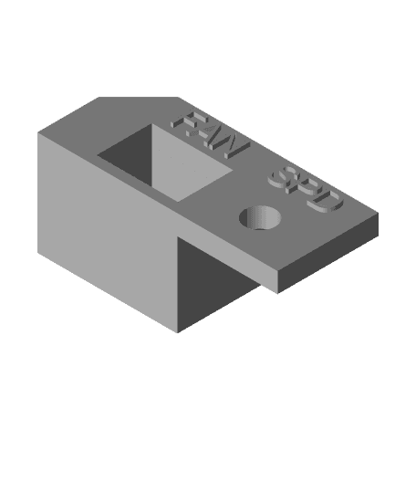
PowerSpec Ultra PWM Fan Switch/Speed Controller

TF Siege Ultra Magnus Thigh Upgrade
SKR_Box v11.stl #SKR_V1.4

Toybox Alpha v1 Klipper Conversion SKR Pico
Ender 3 clone Bigtreetech SKR 2.0 & SKR Mini E3 V2.0 case
Mega Zero 2.0 box for SKR Mini E3
ultra glide spool holder
SKR MINI E3 V3 Adapter plate vor CR-10 V3

Anycubic Kobra Max SKR 3 EZ Adapter

Prusa-Mini Z Bottom for SKR Mini E3
SKR 3 EZ Ender 6 adapter plate
Base skr mini e3 v3 artillery
Top_SKR_Enclosure_TFT35 v6.stl
SKR_Box v8.stl
Skr 1.4 Turbo Cr10s Bracket.stl

Saturn 4 / Ultra / 16k Fan & Duct Adapter
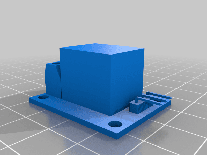
KY-019 Single Channel 120/220v 10A 5v Coil Relay for Arduino / Raspberry Pi
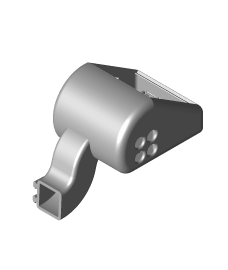
console e3 v10 with 4mm arm G2.stl
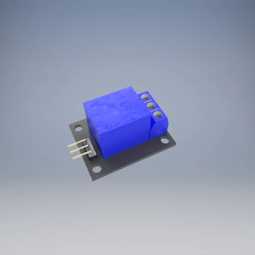
KY-019 Single Channel 120/220v 10A 5v Coil Relay for Arduino / Raspberry Pi