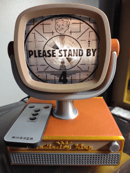


Fallout Radiation King TV Raspberry Pi 4/5 Case.
This is a 17 part (sixteen 3D and one 2D) Raspberry Pi 4/5 case model of a 1950s style television based on the fictional "Radiation King" electronics brand popularized in the Fallout gaming franchise. The television features a fully printable body with the exception of eight heat inserts and twelve screws. The screen can pivot forward and backward at the screen and can also rotate at the neck of the screen support with a hidden printable push pin that allows several wires to safely pass through the neck between the display and the Pi without binding. In this model I use the electronics from an electronic flickering tea candle light and inkjet printable transparent vinyl sticker paper to create the screen design and screen effect. It's not difficult and can be done in just minutes once you have the screen cover printed. Set your 2D printer to print the vinyl in high quality and it works with any standard inkjet printer. You could even use Howard Cooper Western clip from the Fallout TV show.. hint.. hint..
To accomplish this, simply 3D print the screen using transparent PETG at a slow speed. Use the screen part to scan on your 2D printer and get the exact dimensions for the screen vinyl sticker. Print any design you wish, scale it to fit the screen scan area of the screen part, and print. Then place the 3D printed screen on the vinyl sticker print out and trim out with scissors. Finally, place the vinyl sticker on the face of the 3D printed screen. I recommend printing the screen on a smooth build plate. Trim any excess from the sticker on the screen. Be mindful when placing the sticker to avoid air bubbles.
To create the light effect remove the internal electronics from a cheap flickering tea candle light. Cut out the off/on switch but leave the lead to solder later. Use two female to female jumper cables and heat shrink them together in two places. Ideally you want one heat shrink tubed area to align in the open gap between the screen body and the screen support. Cut the connector ends off from only one end of the wires. Feed the wires from the main body after assembly through the neck and up into the screen body. Strip the wire ends, identify the positive and ground leads of the tea light, and solder a wire to each of the tea candle leads. You now have the lighting mechanism. Hot glue this into place, paying attention not to drip hot glue into the wire hole in the neck from the screen body; it could bind it up. You will need to connect the positive to Pin 1 (3.3v) on GPIO header and the other to pin 6 (GND). The light will come on with the pi when it powers up. In my example the tea candle lights had an infrared remote that works through the screen, so you can turn off the screen but not the pi. I include a printable case for a generic remote; you may need to scale it to fit to another rectangular remote.
The screen body requires supports and should be printed back down with the screen body vents on the bed. The inside shouldn't need support but the supports on either side will. The main lower body comes in two flavors: a unibody design and a two part design. The above prototype is the unibody design. Print it with the top down to the bed and suppress supports, if needs-be, in the circle area where the screen support neck goes but only around the outer edge of the circle and not the inner edge. The idea is that the printer will bridge across the outside of the circle to the support on the inner edge to make a much cleaner and flatter area for the neck. Use tree supports on the build plate only. Remember to slow down on silk parts so that outer walls/parameters are printed at 45-50mm/s and keep temp up to 234 degrees C to make it shiny and pretty. The fascia parts, the neck, and the screen support should be printed at 0.16mm layer height. The screen body and lower main body, screen neck pivot pin, and bottom case cover/pi mount should be printed at 0.2mm layer height. The neck pin needs to be printed from PETG; PLA will snap. The feet should be printed with TPU and will require heat inserts to be installed prior to the feet being screwed on. The bottom case lid also needs four heat inserts in the body so the bottom lid can be unscrewed and removed for maintenance. Once the neck pin has been pushed in place, you will be unable to remove it without breaking parts. Post processing should be very minimal. Use super glue to attach the front and rear fascias on the lower body, the screen fascia, the square end of the neck pivot pins and the other ends should snap into the screen body supports. Do not glue the snap-in end or the screen will not be able to pivot forward and backward. Forward and Backward screen movement is purposely limited, but the neck is capable of turning 360 degrees left or right.
I have plans to make it capable of having an actual active display inside the screen body so it can be used without an external display. It will come as a free update. Don't forget to leave a like! 👍😊 It took me some time and a little more than usual prototyping.
Fallout Radiation King TV Raspberry Pi 4/5 Case.

Fallout Dice Tower Can Holder

Towelie Diorama - South Park

Abstract Atomic Era Starburst Wall Decor
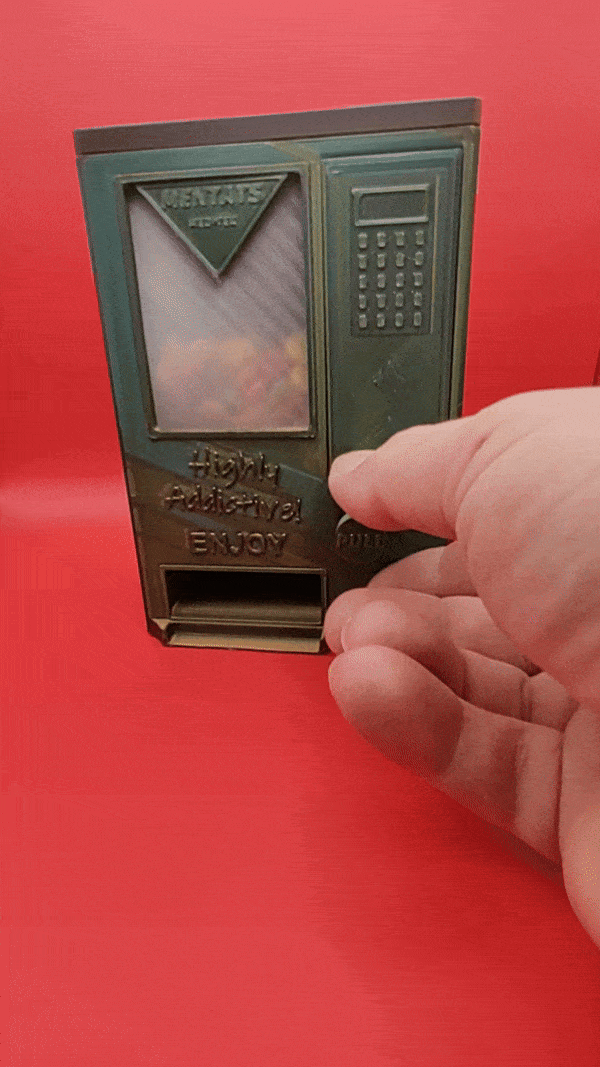
Fallout Mentats Vending Machine Candy Dispenser

Aviator Effects Box – 3D Printable Storage Case
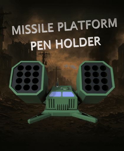
Missile Platform 24 Pen Holder

Fallout Securitron MkIII
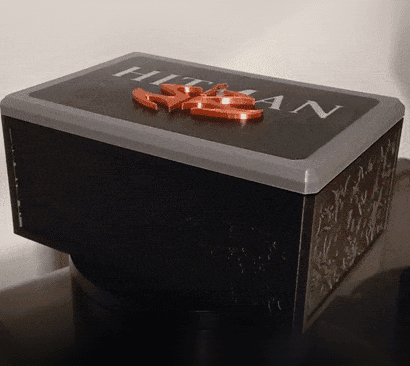
Hitman Skull Box

The Tommy Rose - Thompson Submachine Gun Prop - LIFE SIZE

Fallout Nuka Cola Quantum Cooler Stash Box

Grape Faygo Bucket – TPU Handle

Eskimo Grand Piano Box

Fallout Changeable Billboard - Modular Kit

Arcadia Model 30 - Bluetooth Speaker Stereo
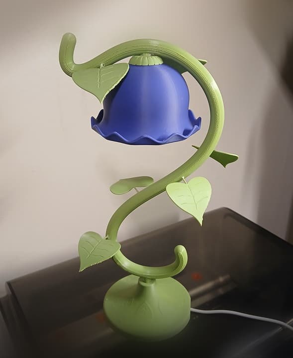
Lumen Lilly Lamp
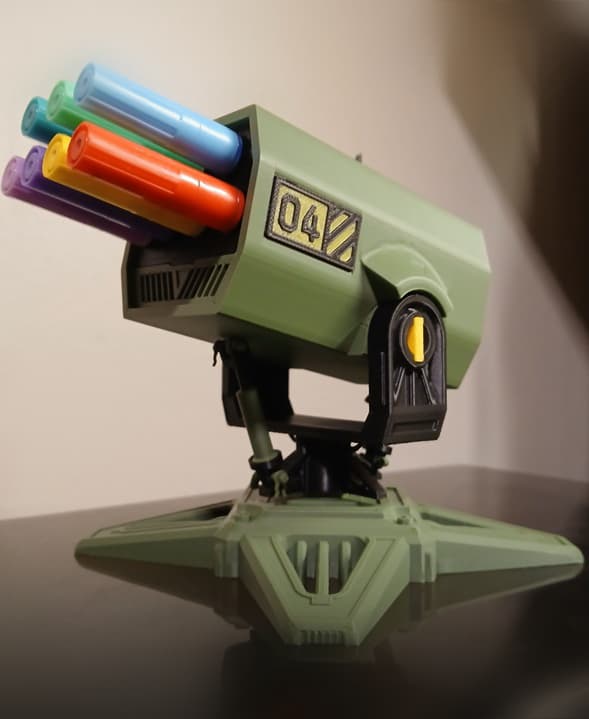
Articulated Missile Battery Pen Holder

ModuStack Drawer System

Everything is FINE Incense Cone Burner

Sunset Sarsaparilla Sheriff Can Holder