Dynamic Shoulder Rotator Cuff Education Model
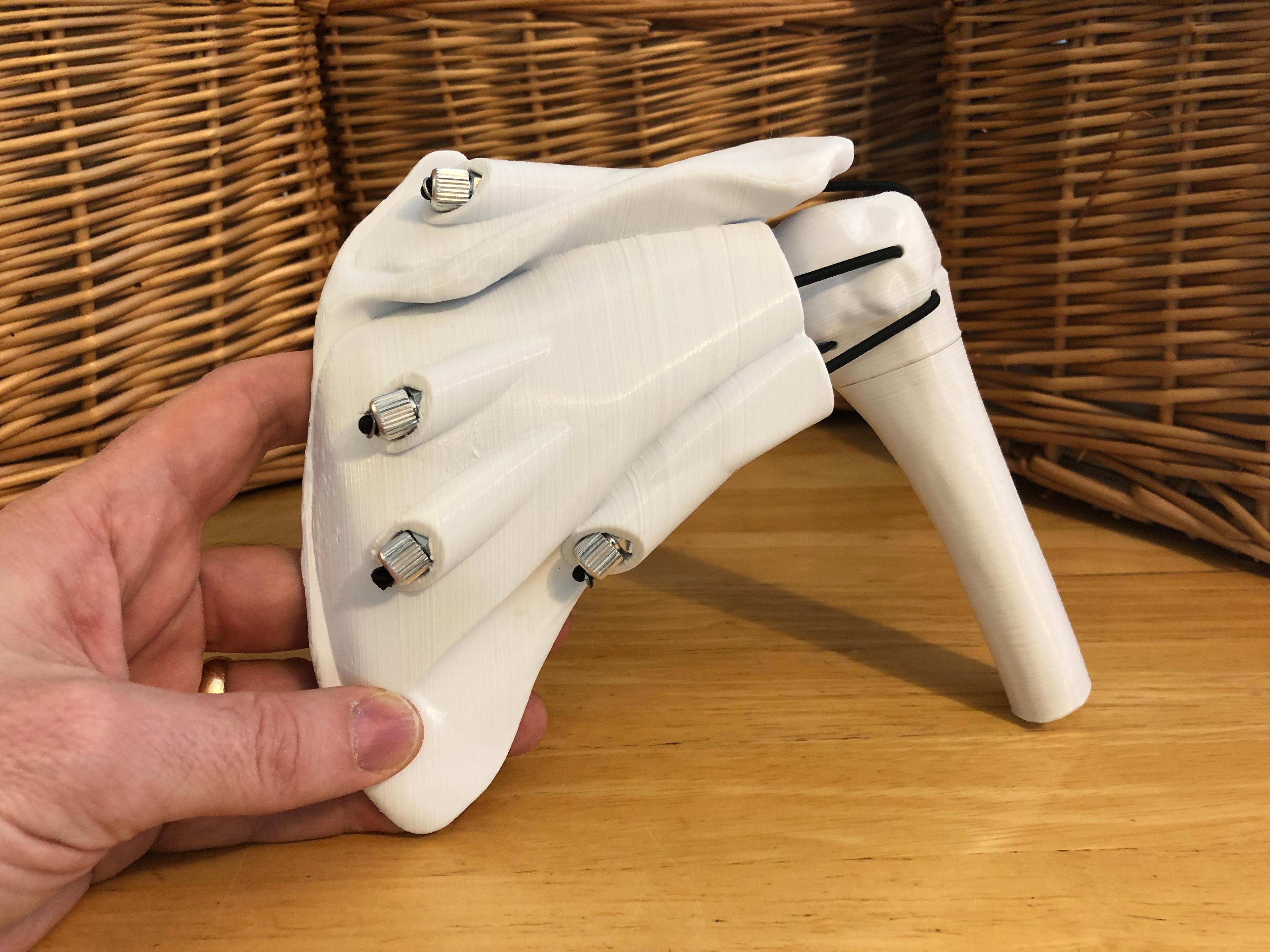
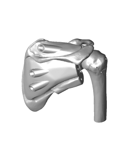
byDaveMakesStuffThis dynamic shoulder rotator cuff model is designed specifically to simulate shoulder dislocations and treatments but it can be used for a range of clinical education applications.
See here for video: https://youtu.be/GVXmNw9ABjo
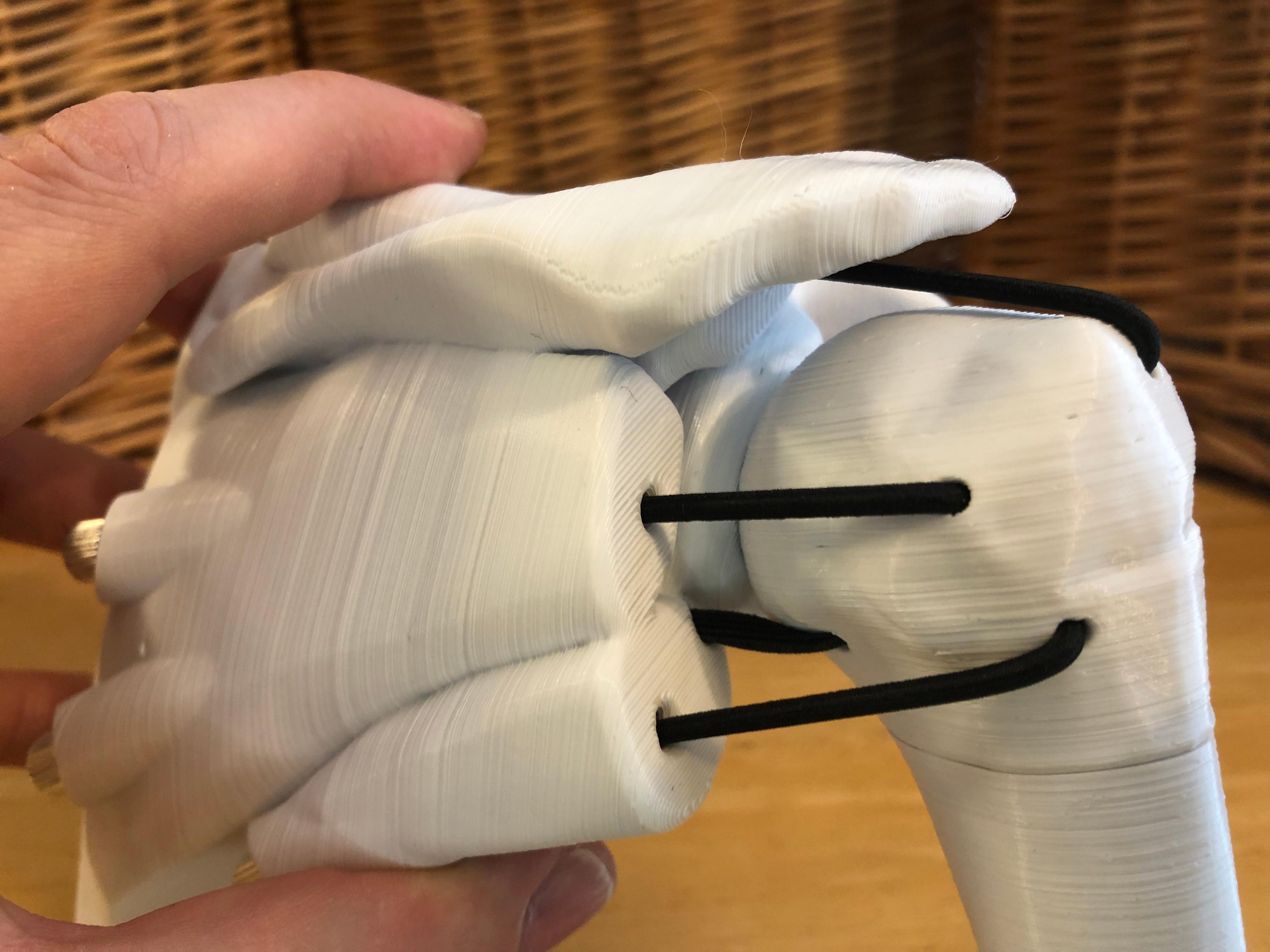
In this model, the humerus is held in place by a series of elastic cords that simulate the pull of rotator cuff muscles and ligaments. Tension on the elastics can be adjusted to simulate variability in rotator cuff integrity and support around the glenohumeral joint.
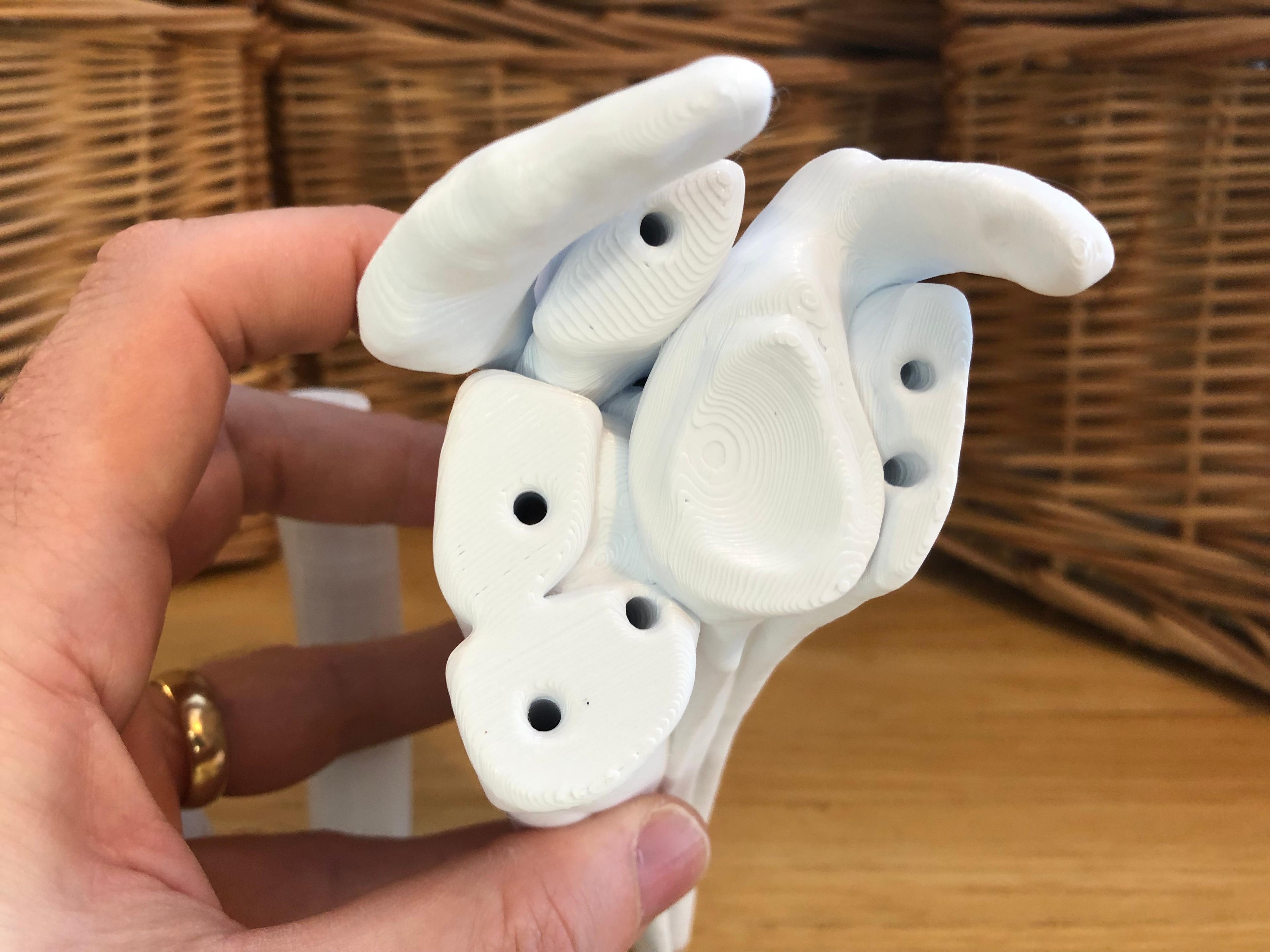
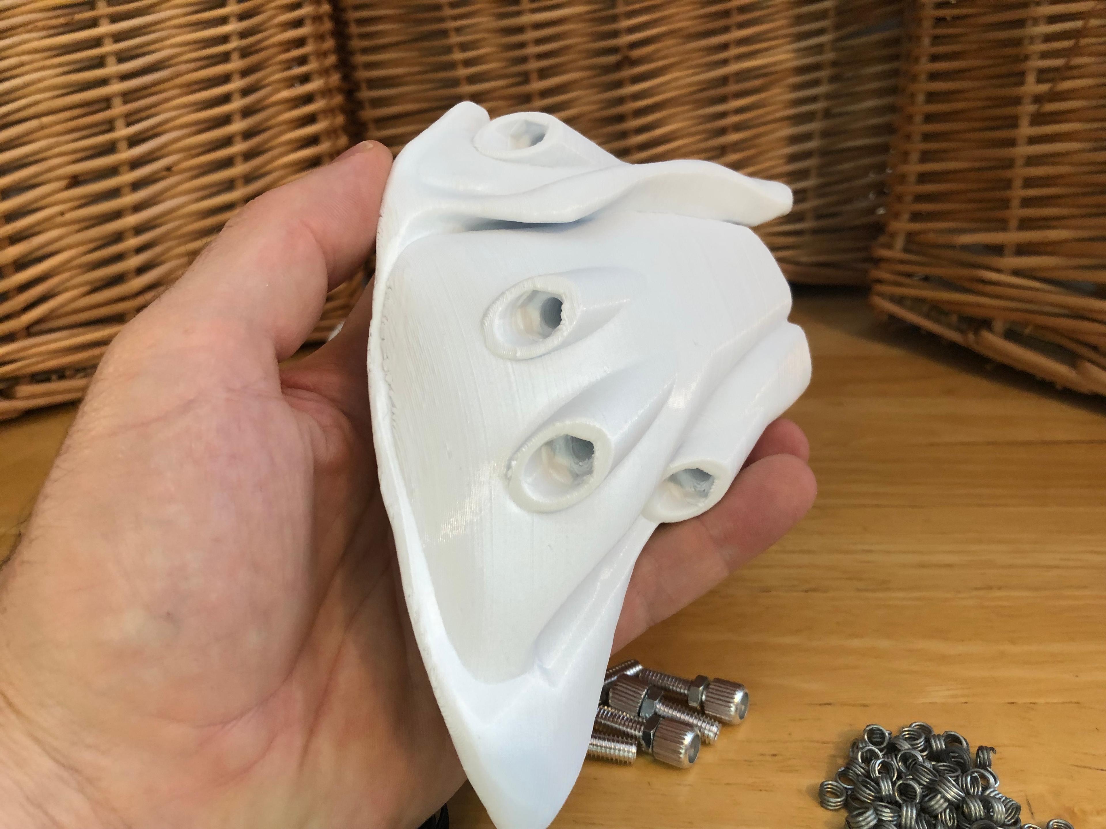
The six anchor points between the scapular assembly and head of humerus represent the major components of the rotator cuff (subscapularis, infraspinatus, supraspinatus, teres minor, and approximations of the anterior and posterior glenohumeral ligaments)
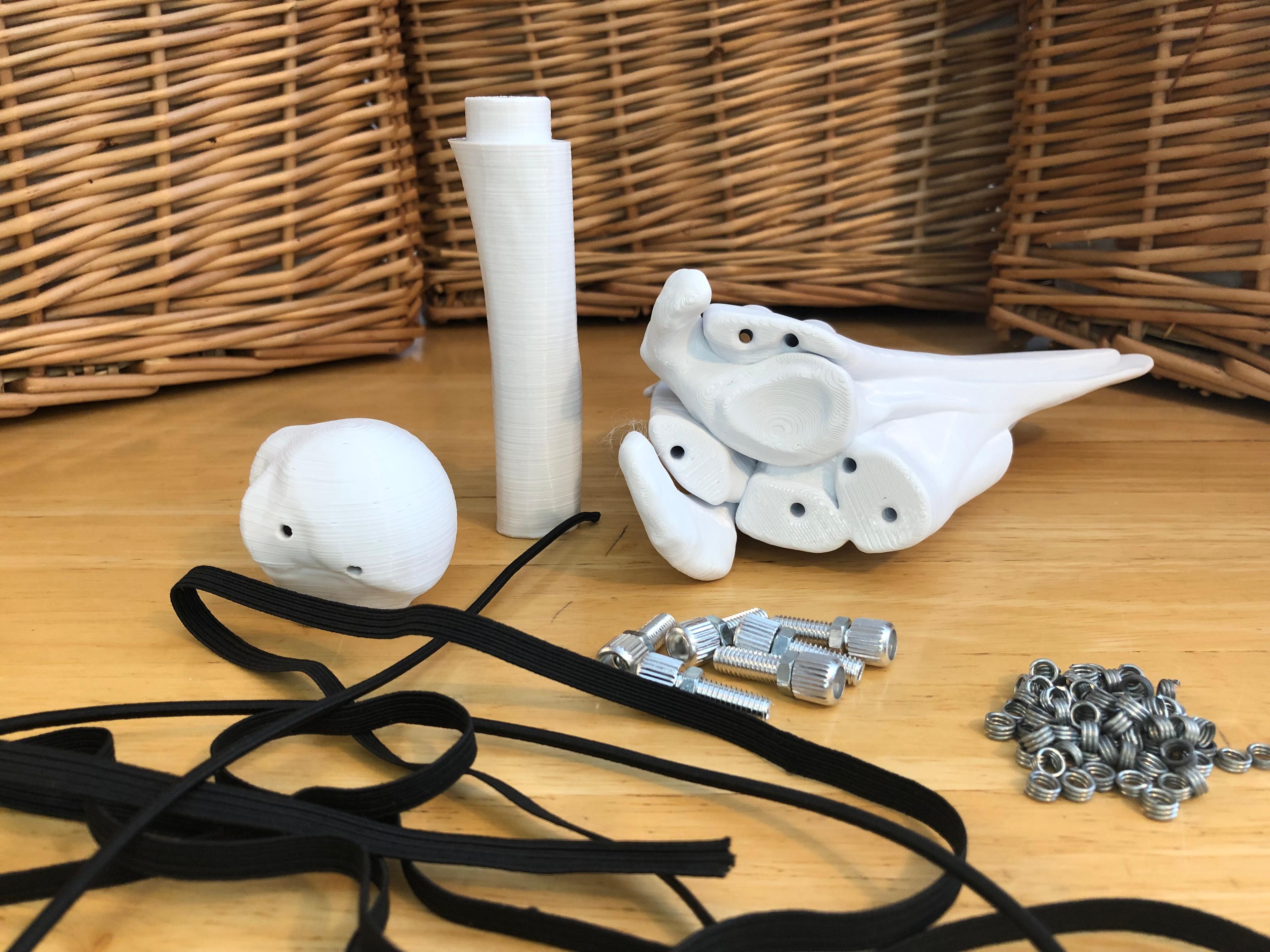
Assembly requires six M6 barrel adjustors and approximately 1m of elastic cord or strap. Additionally, you may choose to use crimps to secure the ends of the elastic.
The M6 barrel adjustors are commonly used in bicycles to adjust cable tension of gear derailleurs. They can be purchased from a bike store or online.
This model shown uses two types of elastic, 1/4” (6mm) wide elastic band, and 1/8” (3mm) diameter elastic cord. While both will work fine, the cord is easier to work with during assembly.
Print the head and shaft of humerus as oriented. Print the scapular assembly as oriented but raise it above the surface of the bed approximately 3mm and build supports up to bottom surfaces and overhangs. It is important that the glenoid surface is oriented upwards so that it prints cleanly.
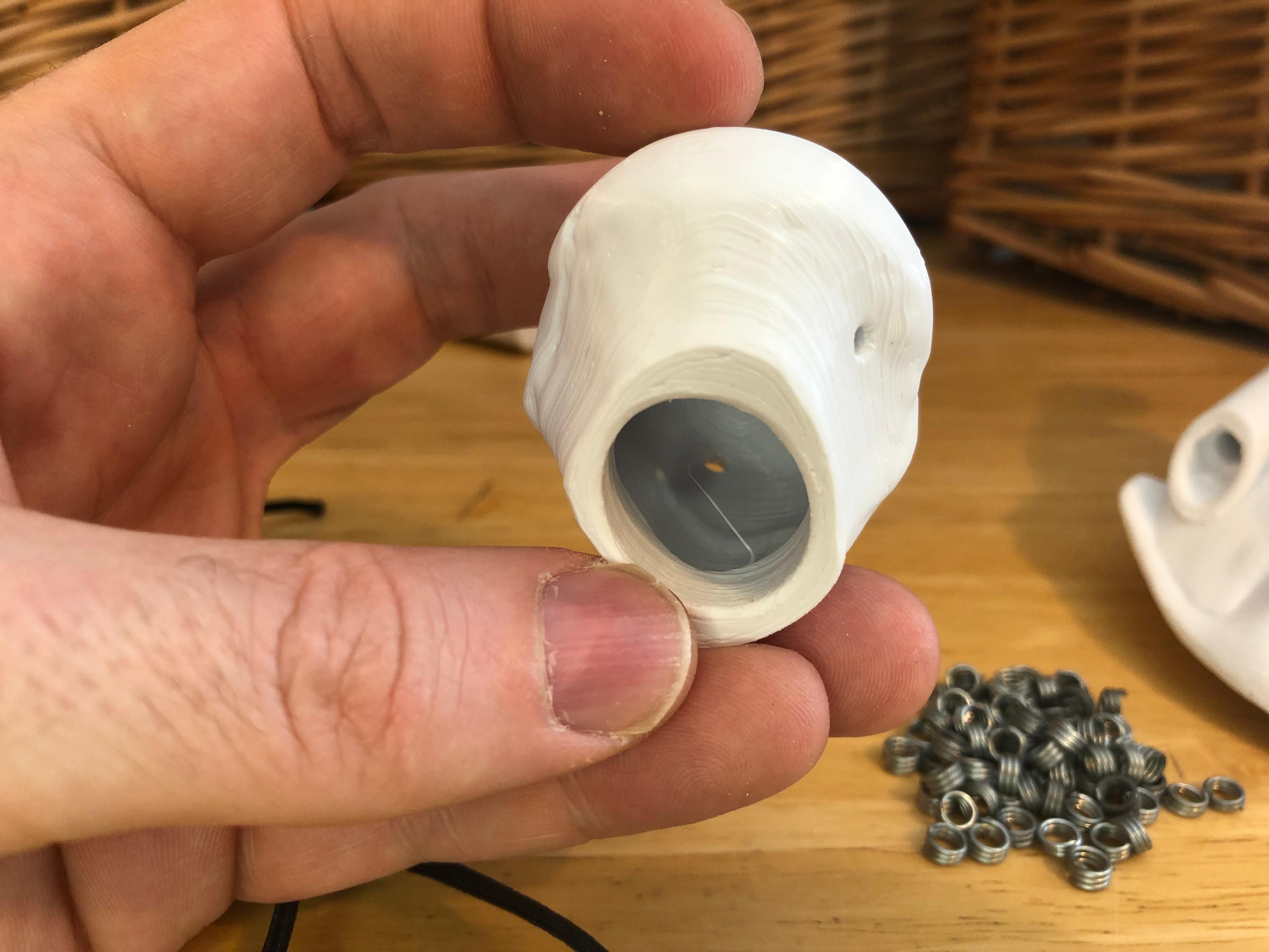
To assemble, begin by passing the first elastic through a small hole in the head of the humerus. Pull it out the large bottom hole and crimp or tie a knot so that the end does not pass back out through the hole. Next, thread the other end of the elastic through the appropriate hole in the scapular assembly and then through a barrel adjuster. Determine what length of elastic achieves the desirable amount of tension and trim the elastic to the appropriate length. Tie or crimp the end of the elastic so that it sits inside the end of the barrel adjuster. Repeat with each elastic.
Once the elastics are in place, insert the shaft of the humerus into the bottom of the head of the humerus. The fit is intentionally tight, so you may have to gently file off the contact surfaces until you are able to insert it in securely.
This model was done in collaboration with Richmond Rescue in Vermont, USA, for use in their training programs. It is intended to support free and accessible open-source learning.
Reference files from: "BodyParts3D, © The Database Center for Life Science licensed under CC Attribution-Share Alike 2.1 Japan".
