Flexible Shaft Direct Drive for Ender 3 CR10S
Model originally uploaded to Thingiverse at https://www.thingiverse.com/thing:3912249.
IMPORTANT UPDATE\NOTICE:
Having spent a lot of time, effort and probably twice the price of a Nimble I still cannot get this to work effectively due to the flexing of the core considerably negating the applied retraction. I am therefore abandoning this thing until as such time I can find something suitable to make work effectively. I have uploaded my more recent side mounted stepper mounted design which uses the speedometer cable below, the design allowing the speedo cable to be cut down to 500mm. But I will not be supporting this any further. The additional uploaded file are purely for anyone that may want them for future reference. cable link:
https://www.amazon.co.uk/gp/product/B00ANLKCP4/ref=ppx_yo_dt_b_asin_title_o02_s00?ie=UTF8&psc=1
4-5mm Coupling used in side mounted version: https://www.amazon.co.uk/gp/product/B07PC3RV79/ref=ppx_yo_dt_b_search_asin_title?ie=UTF8&psc=1
Link to video of side mounted speedometer cable design: https://youtu.be/p3_mwdY8ywI
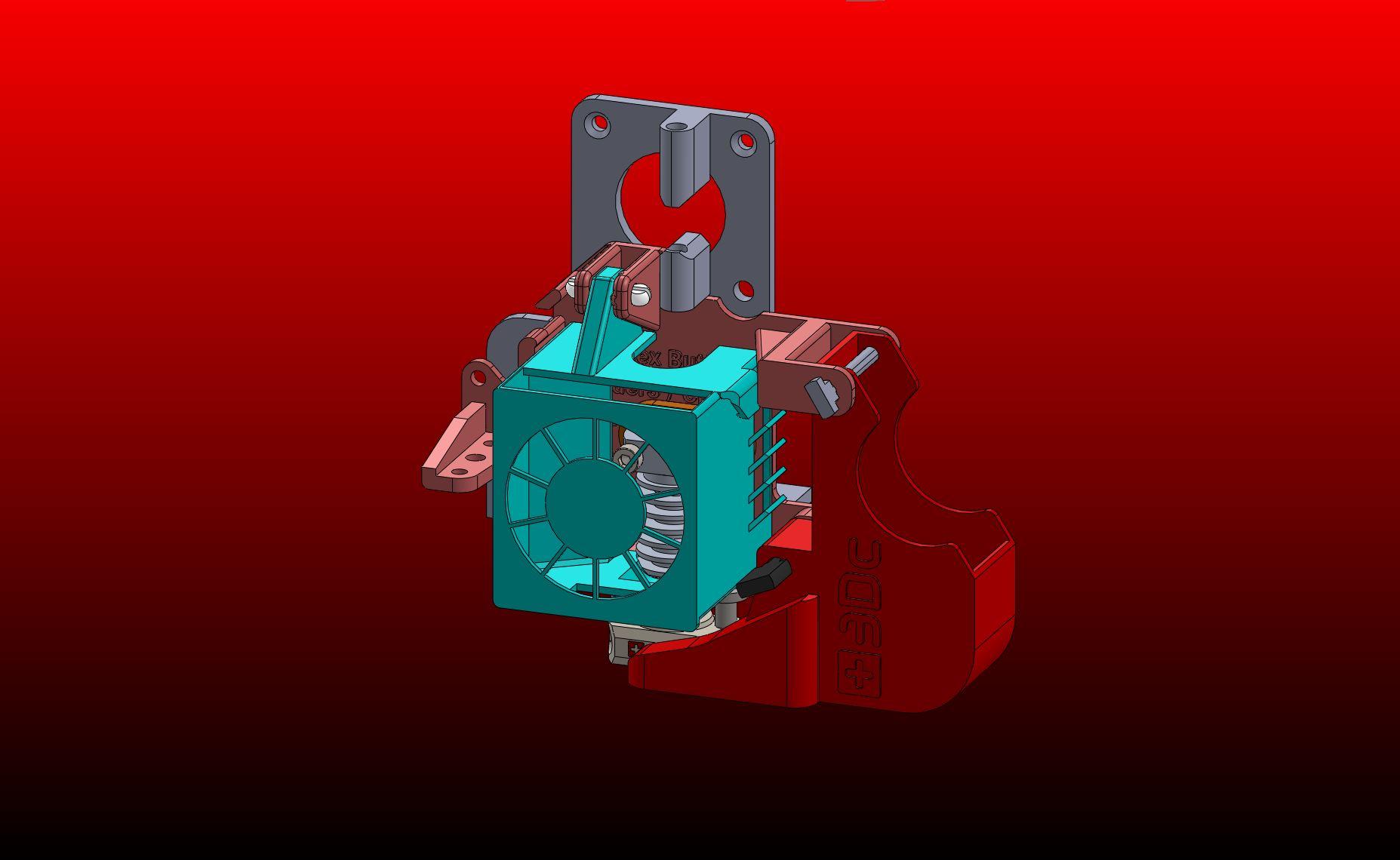
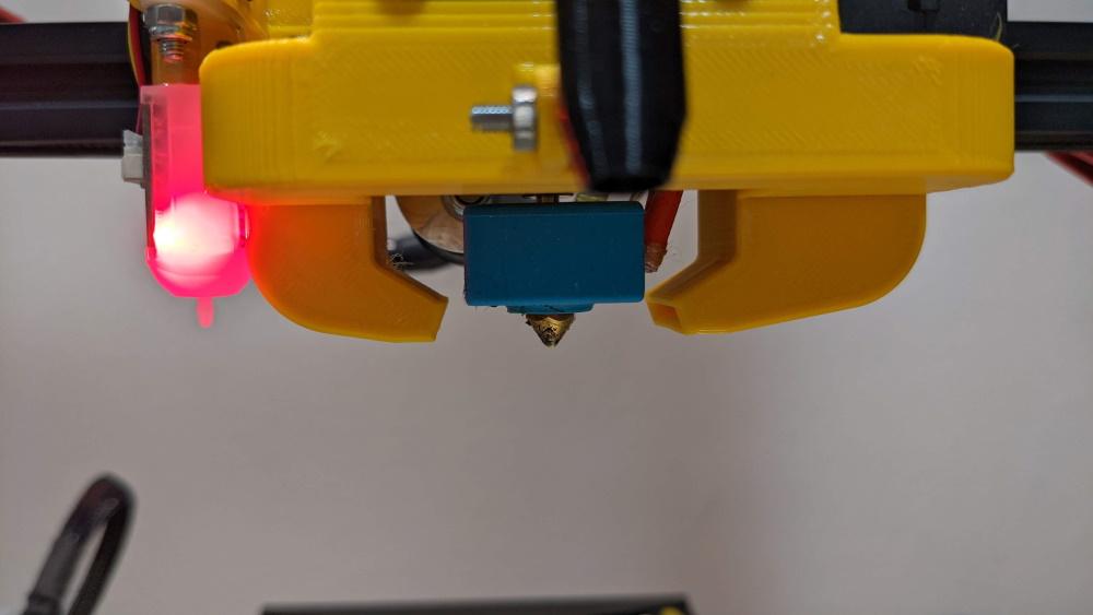
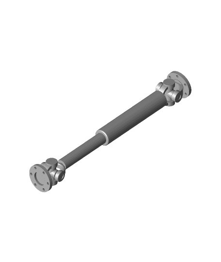
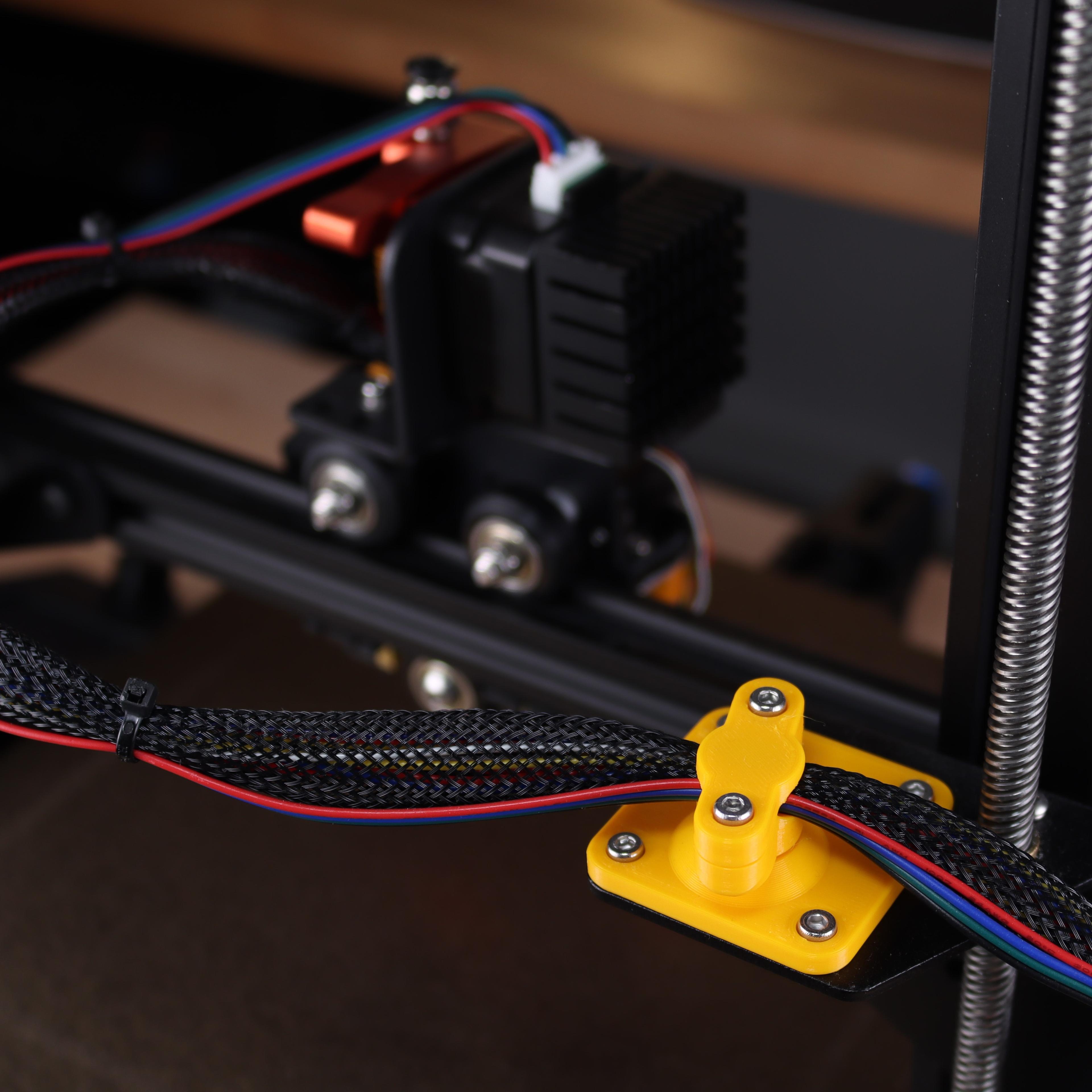
This is a Direct Drive Extruder design which uses a flexible drive shaft to reduce the weight of the Extruder Head. The things works as described but I am leaving the status has WIP for now for further print testing. I will upload some samples when I have tested more thoroughly.
After disappointing results with my own and the Basaraba Direct Drive Upgrade kit due to a lot of ringing- noise artifacts due to the additional inertia of the added motor weight on the Ender 3. I decided to experiment with a flexible shaft drive based on inexpensive readily available components to see if I could improve the print quality.
Overall I have been pleasantly surprised in comparison to previous attempts. Due to the flexing of the shaft there are definitely some quirks with this extruder but nothing some good slicer settings or firmware offsets should be able to remedy. The majority of artefacts seen in tests to date relate more to Retraction and cooling settings. There is less evidence of noise through inertia.
I have uploaded a video to YouTube of the thing in operation, link below:
Components
1.Although most components can be found on Amazon or elsewhere there is a small amount of simple fabrication required, so this thing is not totally Purchase & Print.
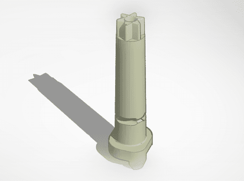
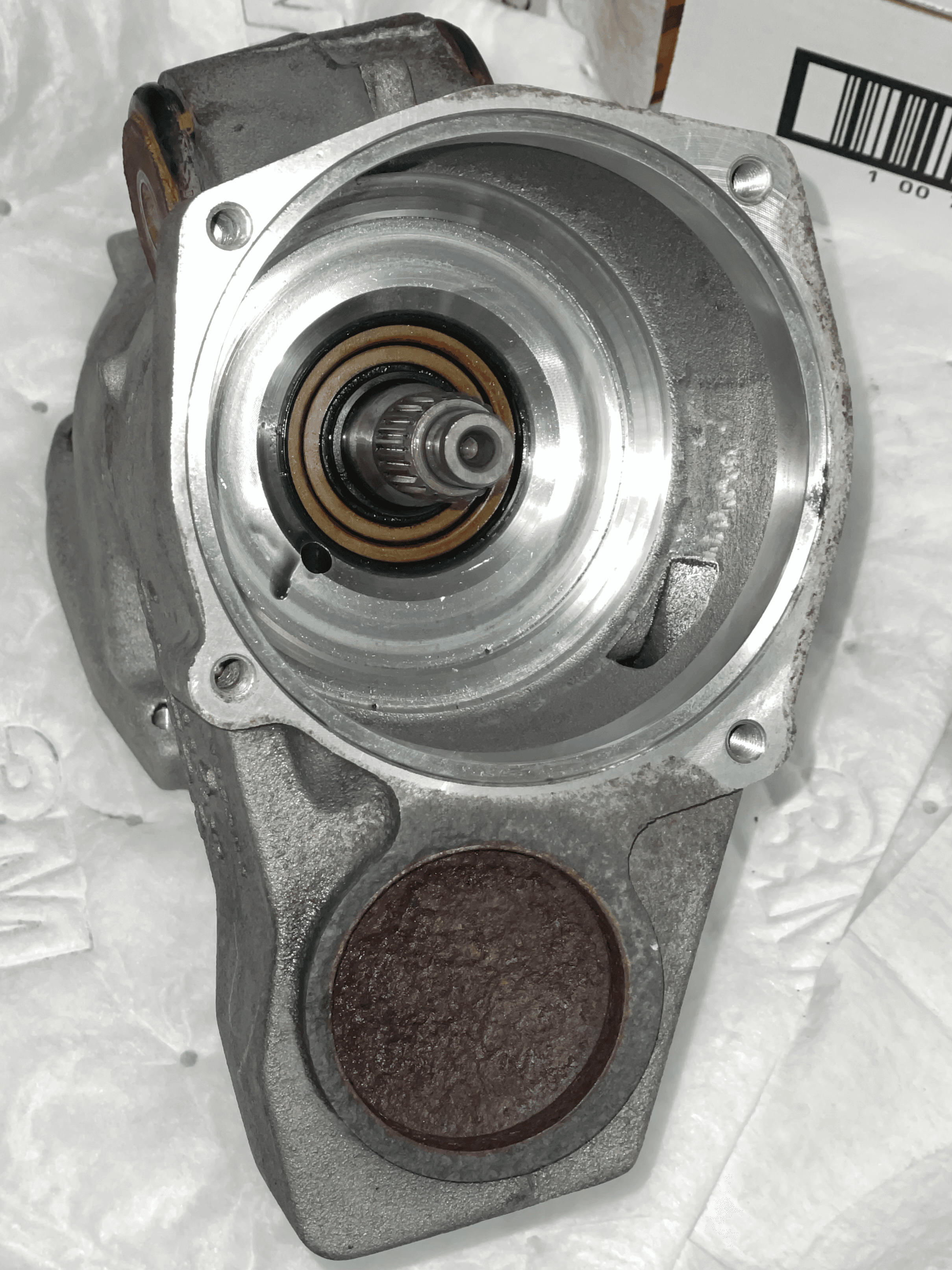
2.I have used the axle, spacers and bearings from an old Nema 17 stepper motor to create the Extruder Head Shaft assembly. This requires some filing and cutting to length so a Hacksaw, file and preferably a bench vice (not essential) is required. I have uploaded a fabrication sketch for the axle fabrication based on a 5mm shaft removed from a redundant stepper motor.
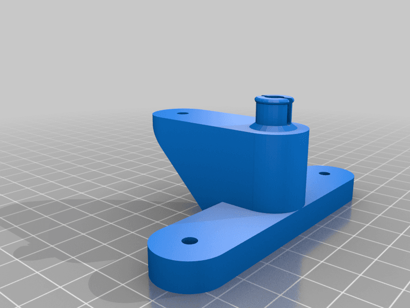
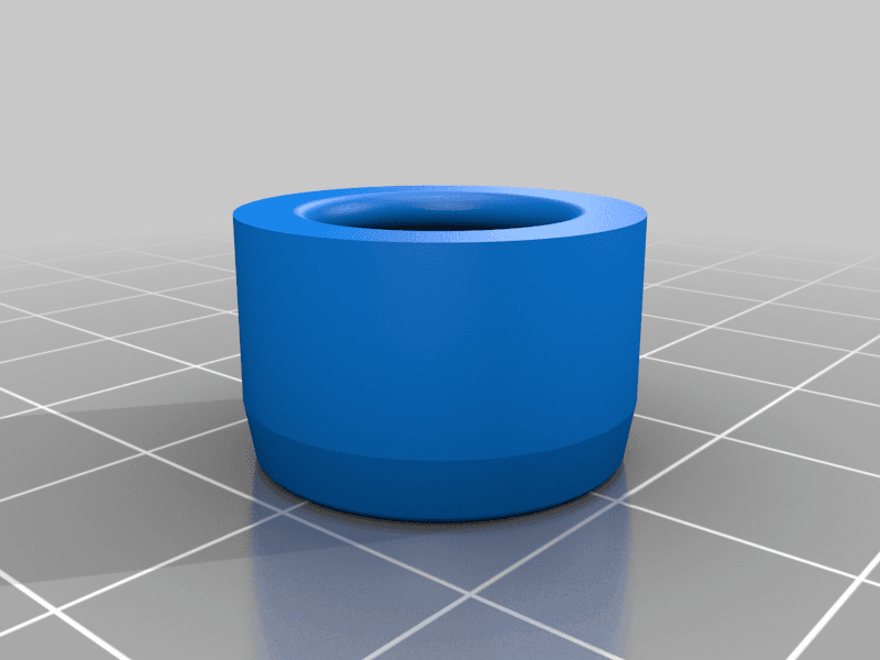
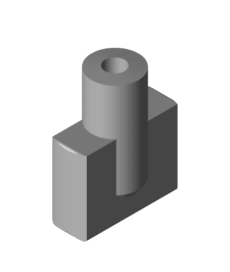
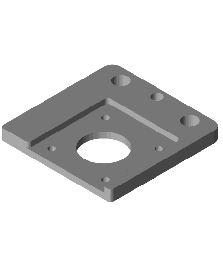
3.The cost of components are from £16.50 upwards (including mounting bracket but excluding filament, nuts and bolts) dependant on how long you want to wait for delivery. The fundamental requirements are a 4mm OD flexible shaft (similar to those used in a Dremel multi tool) preferably with at least one 4mm flat head or spigot coupling to the end and a fairly rigid PU tube with an ID of 5mm and an OD of 8mm. You will also require 2 x 4mm to 5mm shaft couplings and a stepper motor 90 degree mounting bracket. For those who do not have or want to purchase the angle bracket I have uploaded a plastic printable version.
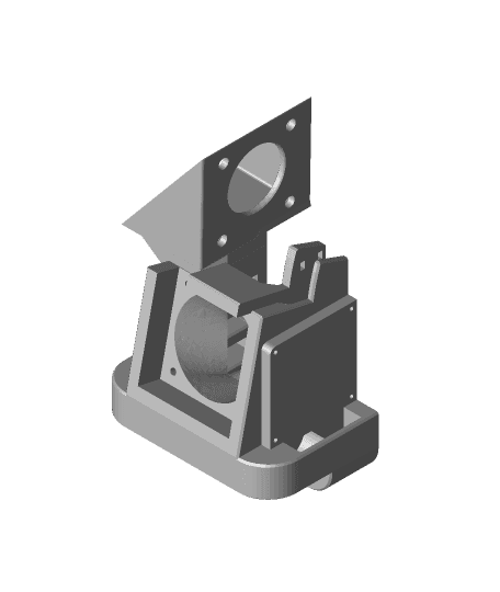
4.I have used the same base design has previous Hero Me remixes so most recent base and ducts should be compatible.
5.Unitil I have completed an installation guide for this thing I have uploaded the guide for the DIY Direct Drive which as a similar assembly for reference.
6.On my Ender 3 I cut the PU tube down to 790 mm long and trimmed the flexible shaft to 750mm long(do not attempt to shape the end of the shaft after cutting, you will destroy it and it will not fit in the coupling). The fin on the spigot end of the flexible shaft will need to be cut off and a 12mm long flat filed on the shaft to help prevent the shaft revolving in the coupling. If using with a CR10S I would suggest (not tried) a tube length of 990mm and a shaft length of 950mm.
7.I will upload an Installation guide when complete. Please comment if there are any immediate queries.
BOM
1.These are the actual components I have used, you will be able to find less expensive, single purchases with longer delivery times if suits.
https://www.amazon.co.uk/gp/product/B07PB2QXZK/ref=ppx_yo_dt_b_asin_title_o04_s00?ie=UTF8&psc=1
https://www.amazon.co.uk/gp/product/B07CN5SGJM/ref=ppx_yo_dt_b_asin_title_o05_s00?ie=UTF8&psc=1
https://www.amazon.co.uk/gp/product/B07PK7HL8F/ref=ppx_yo_dt_b_asin_title_o01_s00?ie=UTF8&psc=1
Print Settings
1.All things except the flex drive bracket will print without supports.
2.I have printed the components at 40% infill, 3 perimeters with Tronsky Orange PETG & PrimaSelect Light Blue PETG. Average printing temp was 240C with a bed temp of 70C.
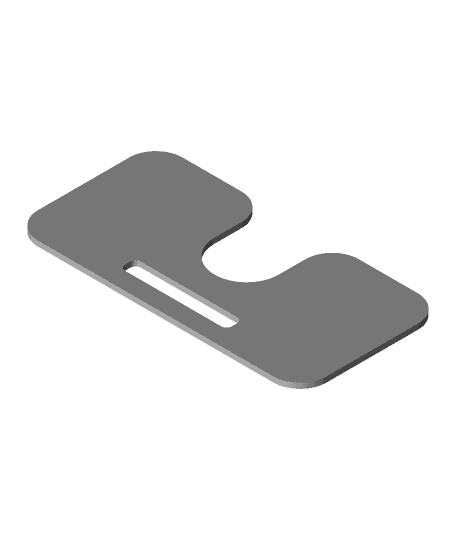
3.I have uploaded 2 versions of the Flexible Drive bracket. One as an additional support pad to allow for interim supports in your slicer to reduce the likelihood of the PETG based supports warping. 4.I have included some sacrificial layers to various holes in most parts to aid bridging when printing. These will require cleaning out prior to assembly.
Operation
Due to the flexing of the shaft there are a few quirks with this thing. I am still testing and have no specific overall conclusions at this time.
1.Retraction - Due to the flexing of the shaft the retraction needs to be higher to compensate. Therefore although a high retraction is set in the slicer the actually received retraction at the extruder head is still much lower. I am still testing this.
What Next?
1.Reducing the overall weight of the extruder assembly, perhaps using a single 5015 duct arrangement and single body duct\bracket if achievable.
2.Extensive slicer tweaking to offset the flexing of the drive shaft.
Flexible Shaft Direct Drive for Ender 3 CR10S

Ender 3 CR10S Multi Direct Drive Extruder with Tool Free Adjustment

Direct Drive & Hero Me Remix 4 for Ender 3 & CR10S
Ender 3 CR10S Hero Me Remix 3 For Basaraba Direct Drive Upgrade
Micro-Swiss-Enders Swiss3Dc-Starlex-Ender-Direct-Drive-Fan-Shroud-A4010-R4020-B3
MicroSwiss Direct Drive CR10S Pro V2 Fan Shroud - PROPER FIT
drive shaft animated v2.stl
Drive Shaft Plug
Thermomix Cutter Drive Shaft
Drive Shaft Coupling for Harbor Freight Neptune RC Boat
Hotend Cable Guide for Direct Drive Ender 3 V2 & Other Creality 3D Printers

hotend direct drive ender 3

Mantua Drive shaft 4-4-0 ho scale trains
Volvo AOC Input Shaft Seal Drive Tool

Creality Ender 7 - Direct Drive Mod

Cable guide Ender 3 direct drive
Ender 3 Direct Drive with Cooling for E3D Titan
Satsana - Linear Rail / Direct Drive Stock for Ender 3v2 Remix
CR10s Pro Direct Drive

Direct drive Extruder bracket (Ender 3 v2 neo)