


Spherical Cams Study
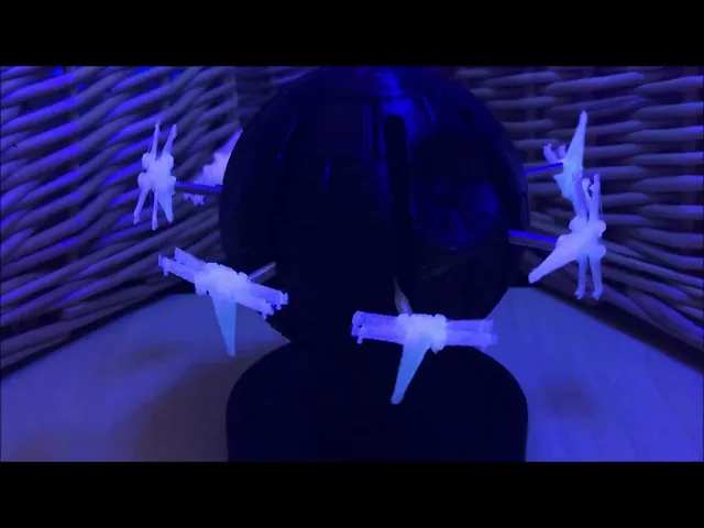
This project is a proof-of-concept study of the potential of spherical cams to create complex coupled movements. See here for videos:
Original: https://youtu.be/yHml-AkOM3U “May the Fourth” Star Wars Remix: https://youtu.be/7f1xcGMAGqo
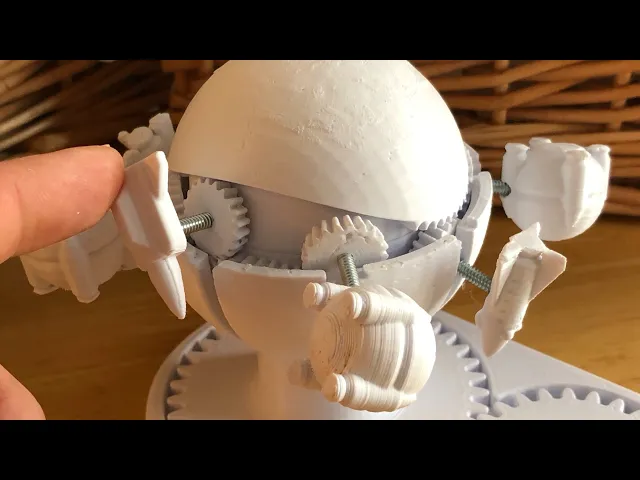
The rotation of the outer shell around the inner spherical cam moves the followers around the equator and back and forth between the poles. Gear teeth within the cam slot creates axial rotation. The design of the cam slot and placement of the teeth allows for creative combinations of these three types of movements.
This model comes with two sample spherical cams and can accommodate up to eight followers.
The “Single Sine” cam moves the followers one complete sine cycle between poles and reverses axial rotation four times for every revolution around the equator.
The “Double Sine” cam moves the followers two complete sine cycles between poles and reverses axial rotation four times for every revolution around the equator.
Printing and Assembly
Print out as many gears as you what, to a maximum of eight. You will need a 3/4” long 1/8” fine thread bolt for each gear. Insert the 1/8” bolts through the gears. You may need to glue these in place.
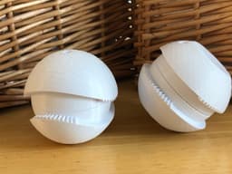
Print the two halves of your preferred spherical cam. Press the two halves of the sphere cam together using a vice. Glue is not needed.
Print one of each of the remaining files.
For best results, consider lubricating moving surfaces with Vaseline or similar lubricant.
Slide the “Outer Shell Bottom” over the upright rod in the “Base.” Lock into place by press fitting the cam onto the hex connector of the base. Ensure that it rotates smoothly.
Insert as many gears as you can into the cam and slots of the bottom shell. Next, insert the remaining gears into the cam and slots of the top shell. This is tricky but doable! If you find that the outer shell pops of during use, you may need to glue it to the bottom shell.
Place the “Drive Gear” into the recess in the base. If you wish, you can secure the drive gear in place by inserting the “Drive Gear Pin” from the bottom.
Add some objects to the spinning followers and your project is finished!
Spherical Cams Study

Large Mizu Gumi Picture Stands

Small Mizu Gumi Picture Stands

Industrial Construction Set - FDM

Bouali Strange Attractor Sculpture

Aizawa Strange Attractor Sculpture
Bio Blob
Flame Lamp
Crystal Lamp
Fidget Ouchies

Tooth Fairy House
Crystal Citadels

Shack Pack - Sober

Shack Pack - Tipsy

Shack Pack - Plastered
Hole Through a Hole in a Hole

Holder for Reusable Straw
Stellar Blooms

Bump Boxes
Cut Crystal Eggs - Set 2