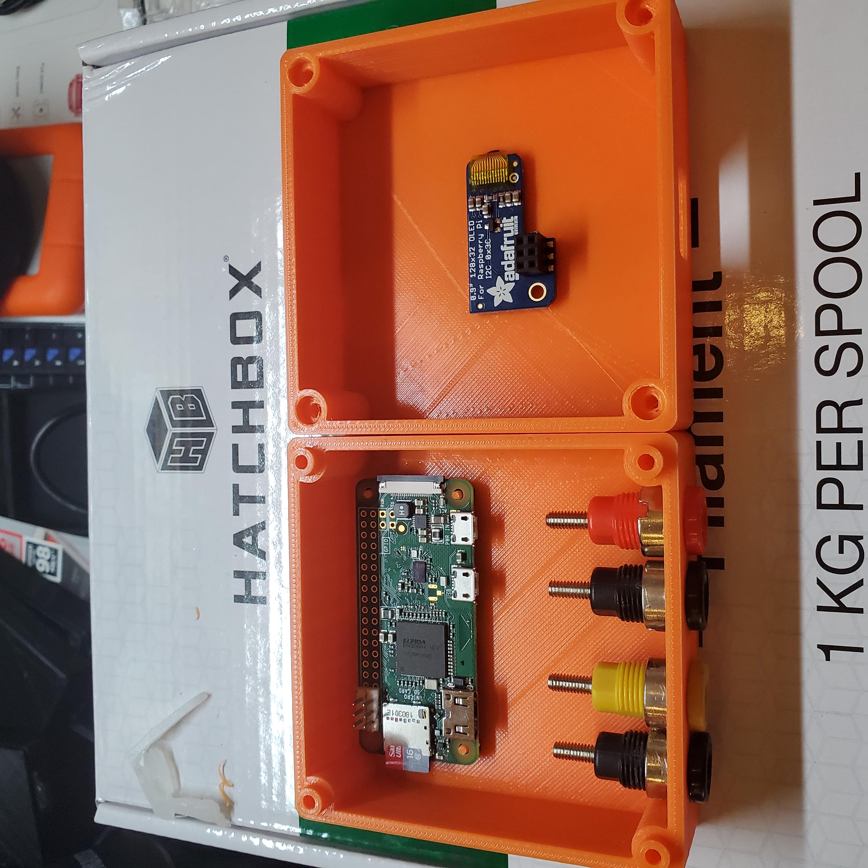
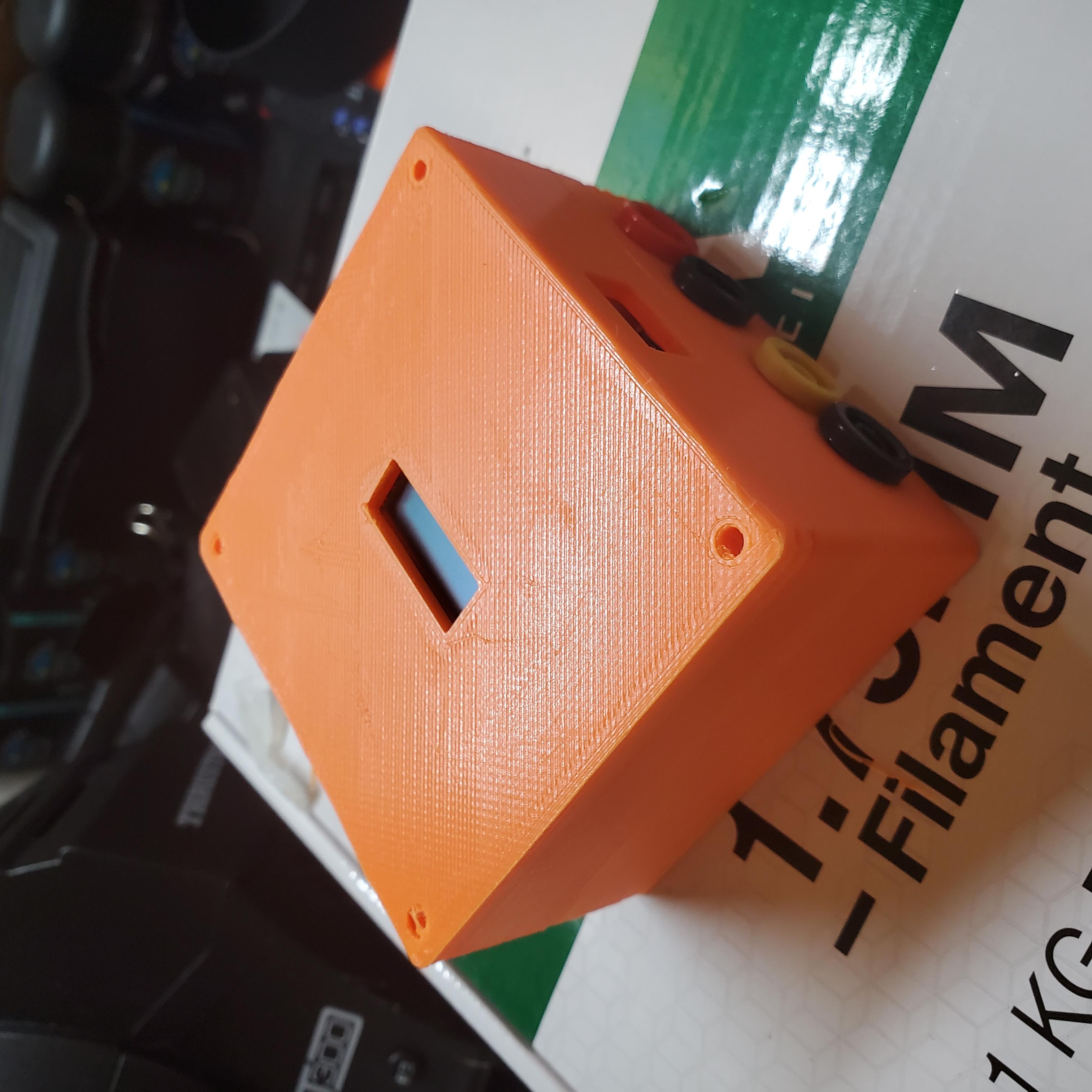
This case is meant to house a RaspberryPi Model Zero-W together with four banana-style connectors and a tiny 128x32 pixel monochrome OLED screen (see: https://www.adafruit.com/product/931)
Its a box that might be over-engineered, but that's okay.
Two of the banana-style connectors can be attached to an existing system which can pull one of the GPIO pins on the RasPi low or high. The second set of banana connectors is soldered to the RasPi's power.
This pull up/down of the GPIO then triggers an SMS notfication (twillio, etc.), or alternatively email, to be sent to the user to notify them of the GPIO's changed state.
This project was originally designed to attach to an existing NON-IOT, moister-triggered water heater cutoff valve to notify me of any leaks in the basement while I'm away.
CHANGELOG -
4/26/2021: Updated the design to fix inner dimensions - Hey Thangs.com admins, it'd be really cool to have some kind of versioning built into this website!
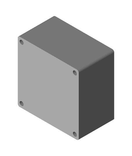
I also removed the snap-fits as my printer has a hard time printing them accurately - I included 4 corner holes that accommodate M3x30mm bolts along with an interior lip around the edge of the top and bottom bodies.
I also added a rectangular cutout on the side of the case to accommodate a male Micro-USB to female USB-A connector so that the USB port is on the side of the case instead of the bottom.
4/27/2021:
I started working on a build-guide for this piece. I'll post a link to the hackaday project page once I get all my notes together...
updated the design again as I ran out of interior volume to lay the wires between the RP0 and the tiny OLED screen. The model has more depth now, which kind of ruins the nice tiny package I had initially. Maybe its time to move away from an ARM based processor to a microcontroller...
I also changed the offset points that help guide the top and bottom of the case together. My previous design didn't come out great once 3d printed. lets see how this design goes...
Moved the cutouts for the banana connectors to the bottom component to make the interior cable/wire management a little bit easier for myself...
The 4 corner holes now accommodate M3x50mm hex bolts with a 5.5x5mm countersink in the bottom for the bolt nuts...


