Hinged mount for BiQu BigtreeTech SKR and Makerbase MKS Gen mainboard in Ender-5
byrmpel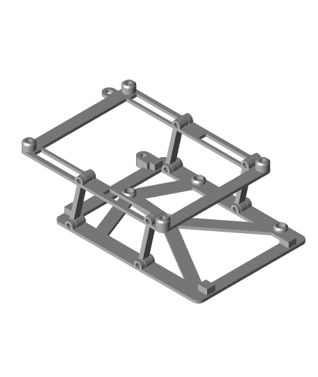
Model originally uploaded to Thingiverse at https://www.thingiverse.com/thing:4768169.
I've seen many controller-board mounts/adapters for fitting an SKR (or MKS) mainboard (four holes in the corners) into a Creality Ender printer.
With all Enders, the screw holes are unique for Melzi boards. For mounting an SRK or MKS in an Ender 3, the most often used solution is to print a new enclosure.
For the Ender 5, the enclosure is large, so often the choice is made to adapt the case rather than print a complete new one. The "solution" is then to Dremel out a few pieces of metal to expose the SD/USB of an SKR/MSK board.
I don't like irreversible changes so I will not alter my case. But I do want to access the SD card for firmware changes. The USB I don't need because I'm using a Raspberry Pi with the GPIO pins 6, 8 and 10 configured for serial connection to the TFT port in the SKR 1.4
To allow access to the SD I first imagined a rotated (along Z) mount but then the cover could not be screwed on.
This thing is the next iteration of over-engineered mainboard mounts.
Once completely assembled and mounted, the mainboard with steppers and their coolers are nearly flush in the case. I have not yet found the perfect solution for that and I don't see where I can win 1 mm to make it fit, but I did not want to wait longer before sharing this design.
Technically, this is a remix because of the mounting points, but in all other ways of viewing it, this is an original design.
for mounting you will need
-
8 m3x10 bolts
-
4 m3x10 headless bolts. (I only had shorter so I used 1 4mm and 1 6mm in each hole Reason for this is to create axles without introducing the possibility of electrical shorts. If you have m3x10 bolts with very flat heads (max 2mm) you can use those, screwed in from the outside.
-
the 4 original screws the Melzi board was mounted with + 4 washers, at least 6 mm outside width
-
1 m3x8 bolt
-
5 m3 nuts This thing consists of 3 parts
- a base. this is the part that will screw on the case.
- 4 swivel arms. these are mounted with the 4 normal bolts, screwed in on the inside, or thin heads (max 2mm) it you want to screw in from the outside.
- a mounting plate. mounted on the 4 swivel arms with either the headless bolts, or the thin-head bolts screwed from the outside. DO NOT screw in from the inside, you will create electrical shorts! You have been warned.
the 5 nuts go in the mounting plate (4) for bolting on the mainboard with (4) m3x10 bolts the 5th nut goes in the base (before mounting to the case)and is used to lock the whole thing when stowed.
assemblyAssembly is TRICKY. Do not do this in a rush, keep your calm.
- take the base and an arm, place the arm in one of the 4 slots. The arms are sort of an arch, make sure the orientation is as shown
- gently screw in the bolt from the inside. It will thread in the base, and should not thread in the arm. If it does, it will only be slight and that will create friction. A little is good, but you should be able to rotate the arm without too much trouble.
- repeat for the other arms
- now take the top plate and mount it on the 4 arms. use headless screws here, or thin head bolts and screw from the outside. Again, be careful.
- fold the contraption up, place a nut in the base and an m3x8 bolt from the top to test-fit the locking. this should also make sure the nut is seated properly.
- unlock and fold the contraption open.
- for each of the corners of the top-part (the mounting plate), place a nut in the recess and screw in the bolt. do not yet attach the mainboard.
- place the unit in the electronics case and screw in the 2 center screws, using a washer on each..
- screw in the two screws on the side, you can use the gap in the mount to stick in the hex key. again, use washers.
- with the unit folded open, remove one of the bolts, keeping the nut in with your finger, place the mainboard over the hole and screw the bolt back in. You might need 3 hands for this, I managed with just 2 ;)
- repeat for 3 other corners. You might wonder; how to get the two bottom bolts out if the mainboard is mounted with the top two (for example) and is now over the bottom bolts; the trick is not to tighten everything up and the mounting plate should be fairly flexible to unscrew the bolt and let it fall between the plate and the mainboard.
- fold up the unit, lock it with the m3x8 bolt.
Your mainboard is now ready for all the wires.
To access the SD;
- unlock (don't drop the bolt)
- swivel up
- access SD
when done
- swivel down
- lock.
If you like it, click the like (heart) If you print it; post a make If you have suggestions for improvements, questions, any kind of remarks; leave a comment
Looking at the download statistics, you guys and gals out there really like this thing :) so, leave a like, a make, a comment. Much appreciated!