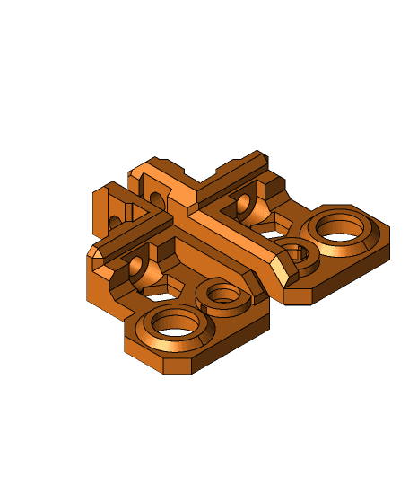
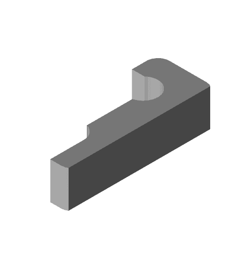
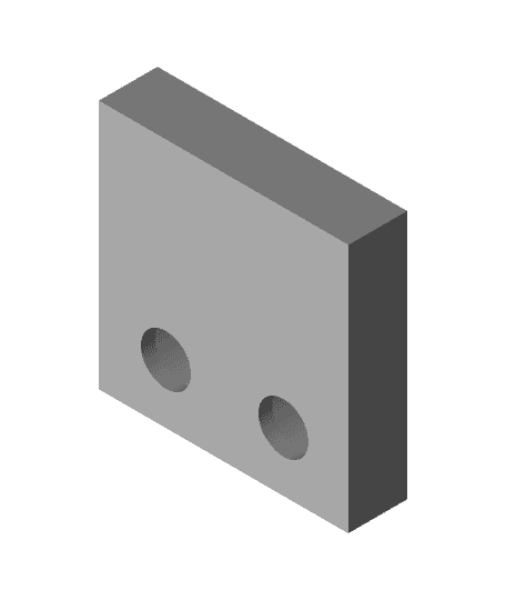
Prusa i3 MK3 Y-Axis Motor Holder with End Stop
Model originally uploaded to Thingiverse at https://www.thingiverse.com/thing:2974262.
EDIT (2018-12-03) : I NO LONGER RECOMMEND THIS PART for users running recent Prusa firmware; this part adds a small margin of offset from the dimensions of the Prusa design so that the “endstop” impact point will be on this part and not the bearing as in the original design. One user has reported that recent Prusa firmwares detect this offset during XYZ calibration and treat it as an error. It is possible that reducing this offset could resolve this issue, but as I have converted my MK3 over to the Bear frame, I no longer have a way of verifying this. My apologies to anyone who wasted time and filament on this part only to find this issue. All I can say is that it worked great until someone at Prusa decided to Add what I consider an unnecessary check to the firmware .
The plastic parts that Prusa ships with their i3 MK3 printer are printed with minimal infill (some reports as low as 10%). The designs are also a bit thin. As a result of these two things, some parts flex more than is desirable.
I had printed and was using this replacement motor mount:
https://www.thingiverse.com/thing:2777432
I had opted to drill the 3rd hole in the frame for this.
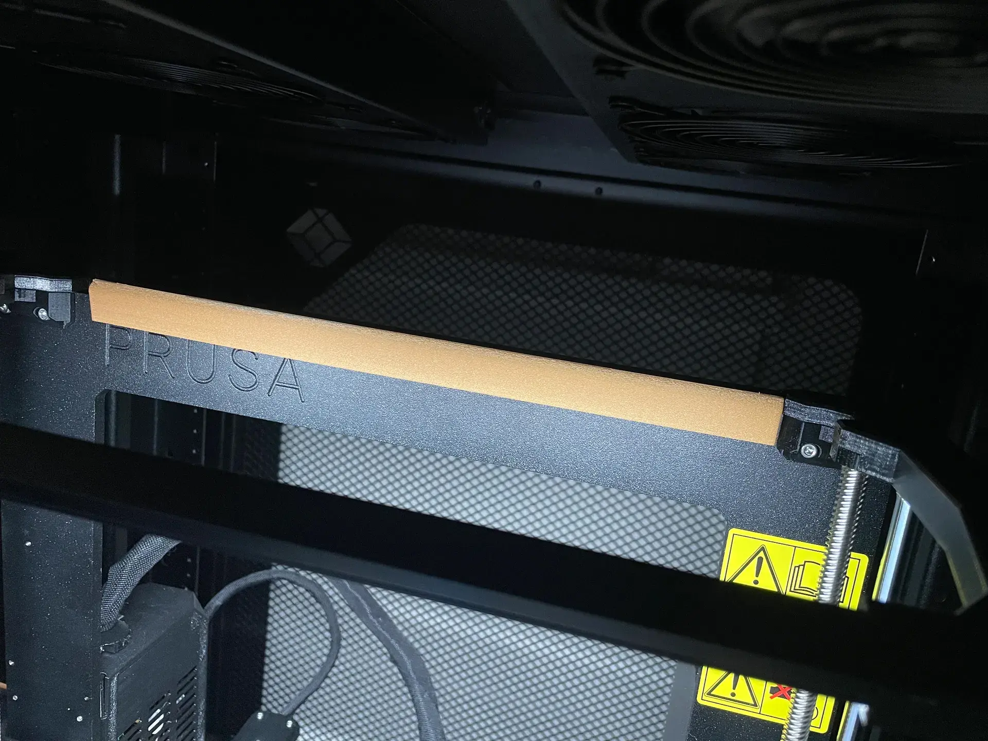
Another MK3 design choice that I was not happy with, was the choice to use one of the y-axis bearings as the end stop for the y axis. Every time the y-axis collides with this bearing, there is some twisting of the bed and the potential to move the bearing out of position.
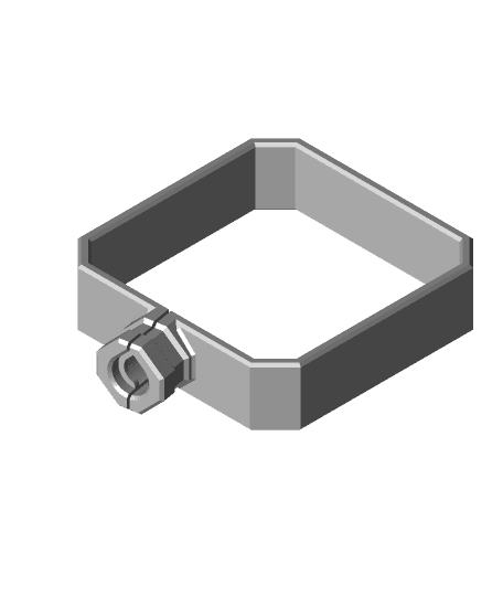
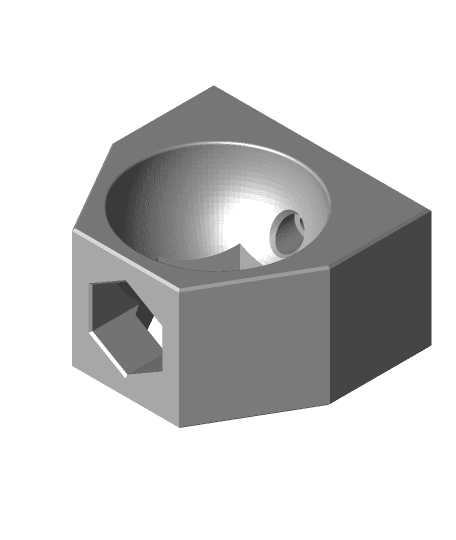
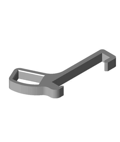
User jltx created a modified motor mount that uses it and the belt holder together to create an alternative y-axis end stop. I wanted to combine both these ideas. Unfortunately, I didn't have access to CAD files for either, but I was able to find an older version of the "juiced" motor mount, and using some measurements of the end stop, create my own.
To attach the bracket to the motor, re-use two of the M3x10 screws from the Prusa bracket. The new motor mount hole (the one closest to the top when the bracket is installed) requires an M3x8.
To attach the bracket to the frame, you can re-use 2 of the M3n nuts from the Prusa bracket. You will need M3x12 screws instead of the M3x10 used in the original. Use of the 3rd hole is optional, and requires drilling a hole in the frame. If you want to do this, you can flip the mount around the other side of the frame, attach it via the 2 holes that are already there, and use the 3rd hole as a drilling template.
Prusa i3 MK3 Y-Axis Motor Holder with End Stop

Prusa MK2.5S mods for Wham Bam Mutant V2

Prusa MK2.5S mods for Wham Bam Mutant V2
Original Prusa i3 MK3 X-axis motor cable strain relief w/Prusa logo
Squash Ball Feets for Prusa i3 MK3 (3030 profile)
Prusa i3 MK3 LED Light Bar Clip
Z Top with 688 Bearings for Prusa i3 MK3 Full Bear Upgrade 2.0
Prusa i3 Mk3 Bowden tube guard for frame edge
Prusa i3 MK3 Raspberry Camera Mount bottom cable
Star Wars Fan Cover for Prusa i3 MK2.5 & MK3

Original_Prusa_i3_MK3S_MK3_platform.3mf

Original_Prusa_i3_MK3S_MK3_platform.3mf
Original_Prusa_i3_MK3S_MK3_platform.3mf
Original_Prusa_i3_MK3S_MK3_platform.3mf

Original_Prusa_i3_MK3S_MK3_platform.3mf

Original_Prusa_i3_MK3S_MK3_platform.3mf
Prusa i3 MK2 Y axis motor support
HMG7.3 i3 Clone X End Stop V3.stl

The Tram & Tram Stop (Compatible with LEGO Motors)
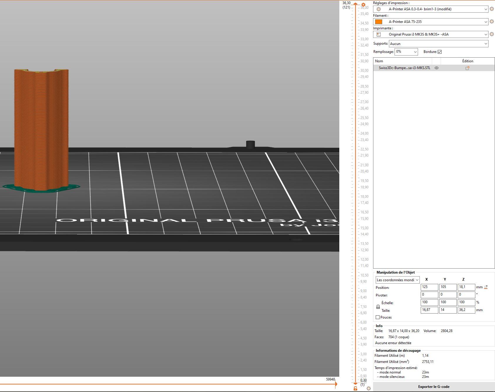
Prusa-i3-MK3S+ Y Axis right shaft End Stop Bumper 36.2mm upgrade