Model originally uploaded to Thingiverse at https://www.thingiverse.com/thing:4742032.
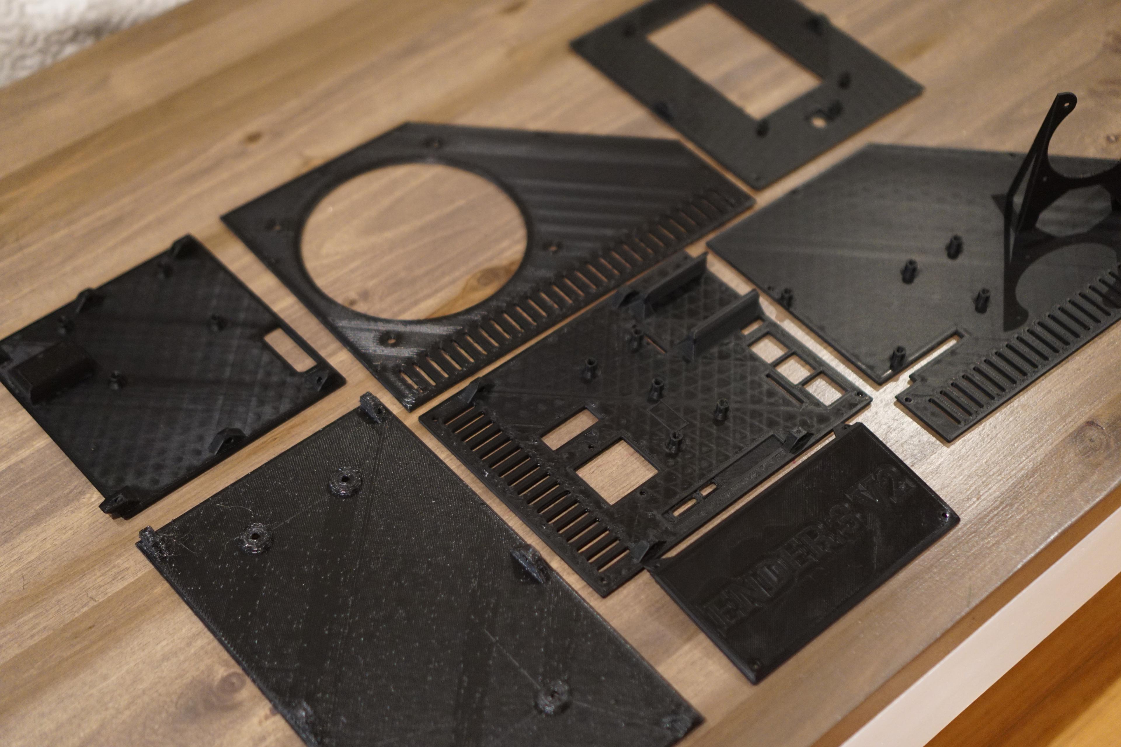
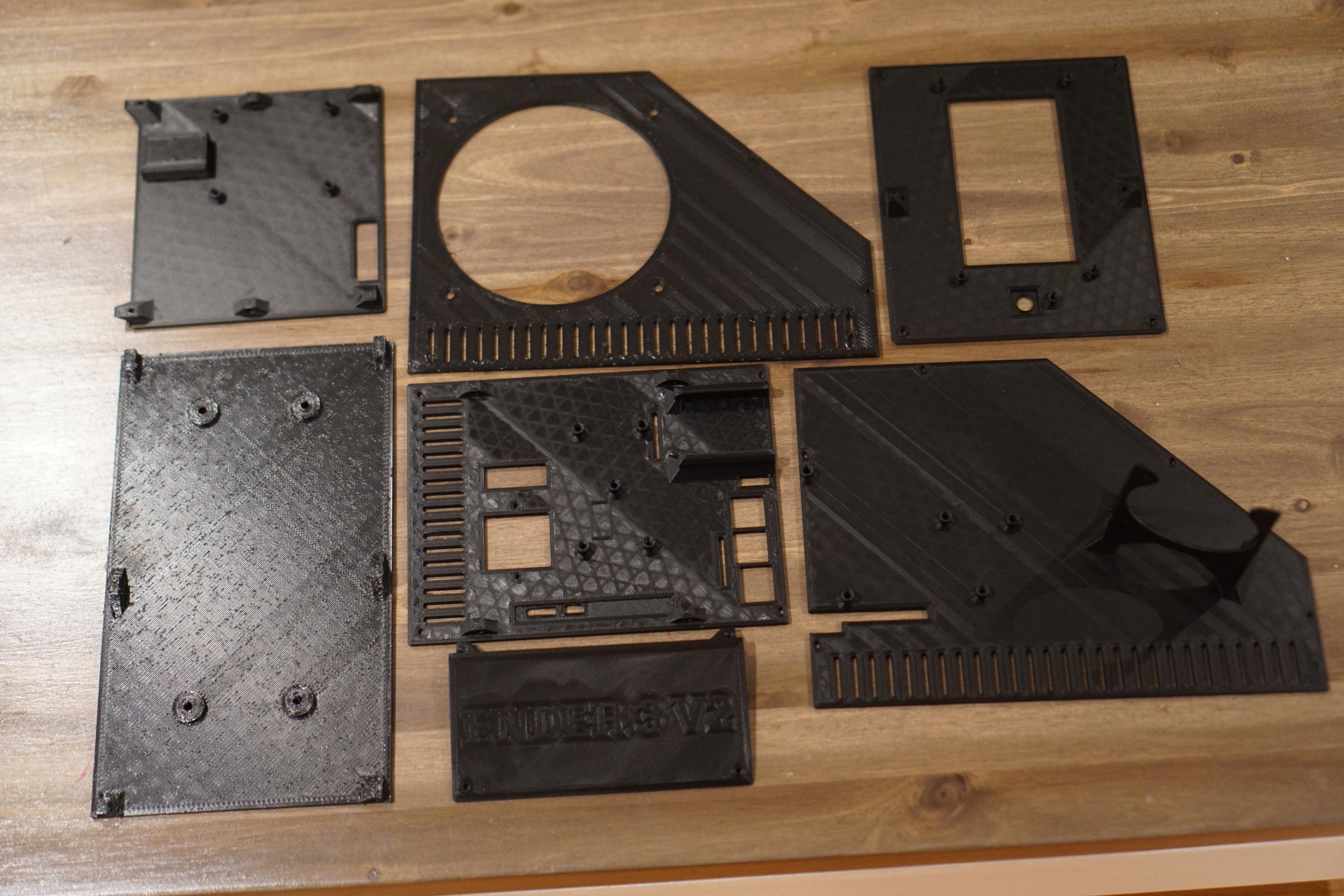
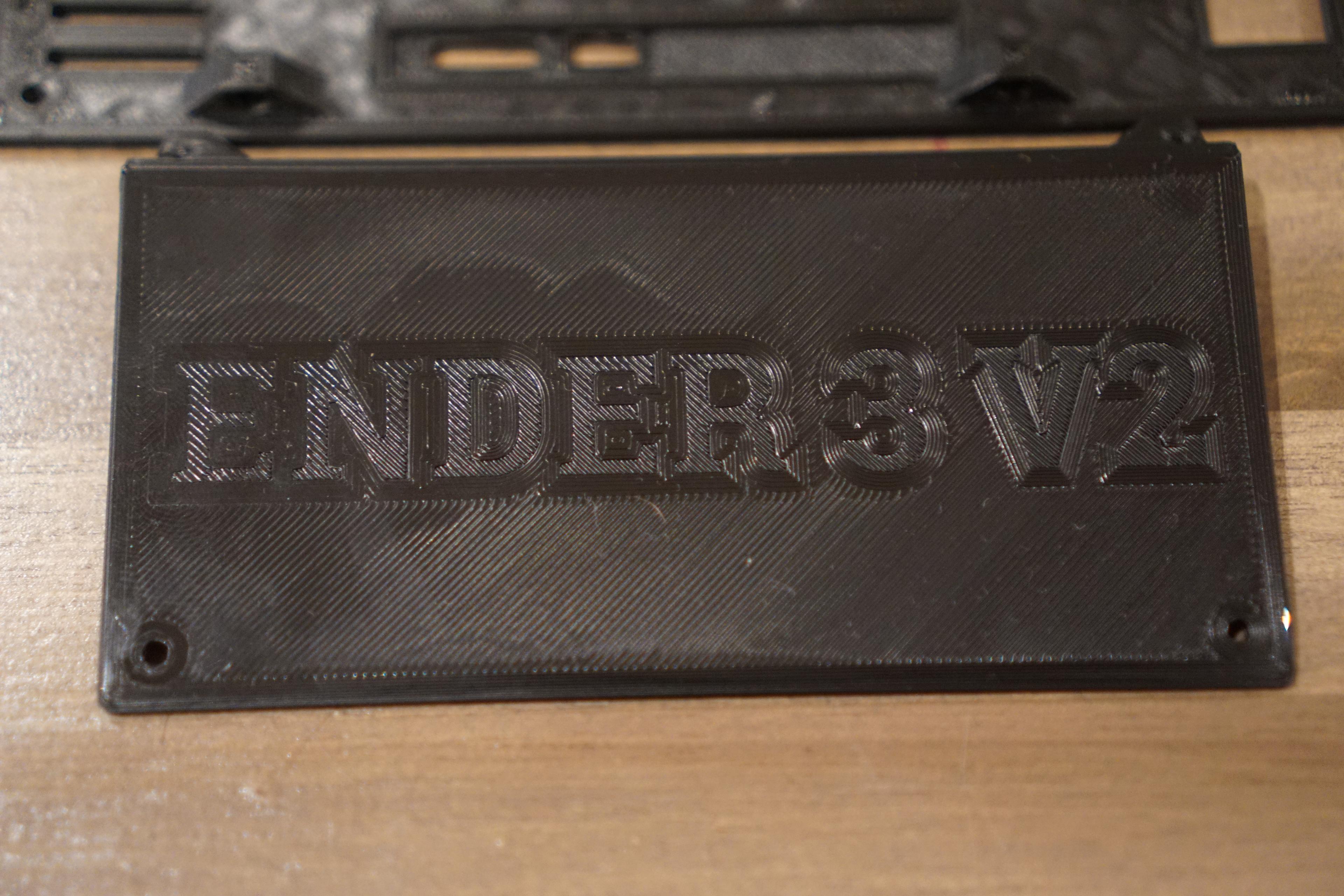
Ender 3 V2 enclosure
If you plan to make this, I don't take any liability if you hurt yourself, working with on open power supply can be deadly. If you are uncomfortable with the PSU open, keep the lid on and install it and see if it can still cool the PSU will most likely still work.
- If you are printing this on an ender 3 V2 you need to have a custom firmware installed so that you can use the full bed size. 233mm is the longest panel. Stock firmware will only go up to 220mm. This is the guide that I followed to install a custom firmware. https://www.youtube.com/watch?v=y87P7K5DTMU&ab_channel=ruiraptor
- I have added some firmware for anyone that can't get the compiling to work FYI If you are using Octoprint, update the bed size there as well.
Please centre the glass on your bed so the print doesn't go over the edge. Home your printer and with the move command move the x axis to 0 and check if it’s close to the edge and then move x to 235 and see if the nozzle is at the edge or over. Move the glass plate on the bed and then check again until the nozzle is not overhanging.
With the large panels alter your start gcode not to print a prime line, don’t forget to save your original one. Just a thought you might just be able to pick the prime line off the bed before it prints the panel.
Please add a wire from the ground terminal to the printer frame for safety.
Any 120mm fan grill should fit just fine over the fan if you want the fan covered.
Please check notes section below for any changes that i have made.
Estimated weight and printing time with 0.4mm nozzle at 70mm/s - 384g / 39 hours Estimated weight and printing time with 0.8mm nozzle at 50mm/s - 307g / 15 hours
You'll need 37x M3x5-8mm screws. You can use long ones in some places but make sure there is enough space for them. 4x M3x20 screws for the internal backup fan 14x M3 nuts. Use these are spacers for the Pi board and screen as the screws will bottom out, you'll need more if you want to mount a buck to the top.
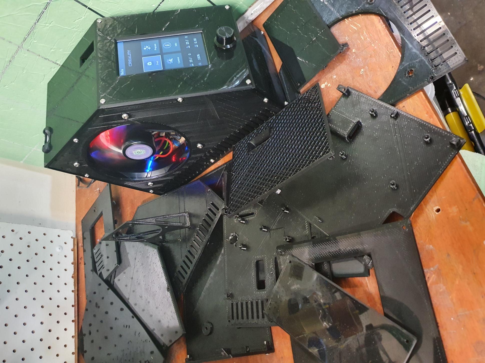
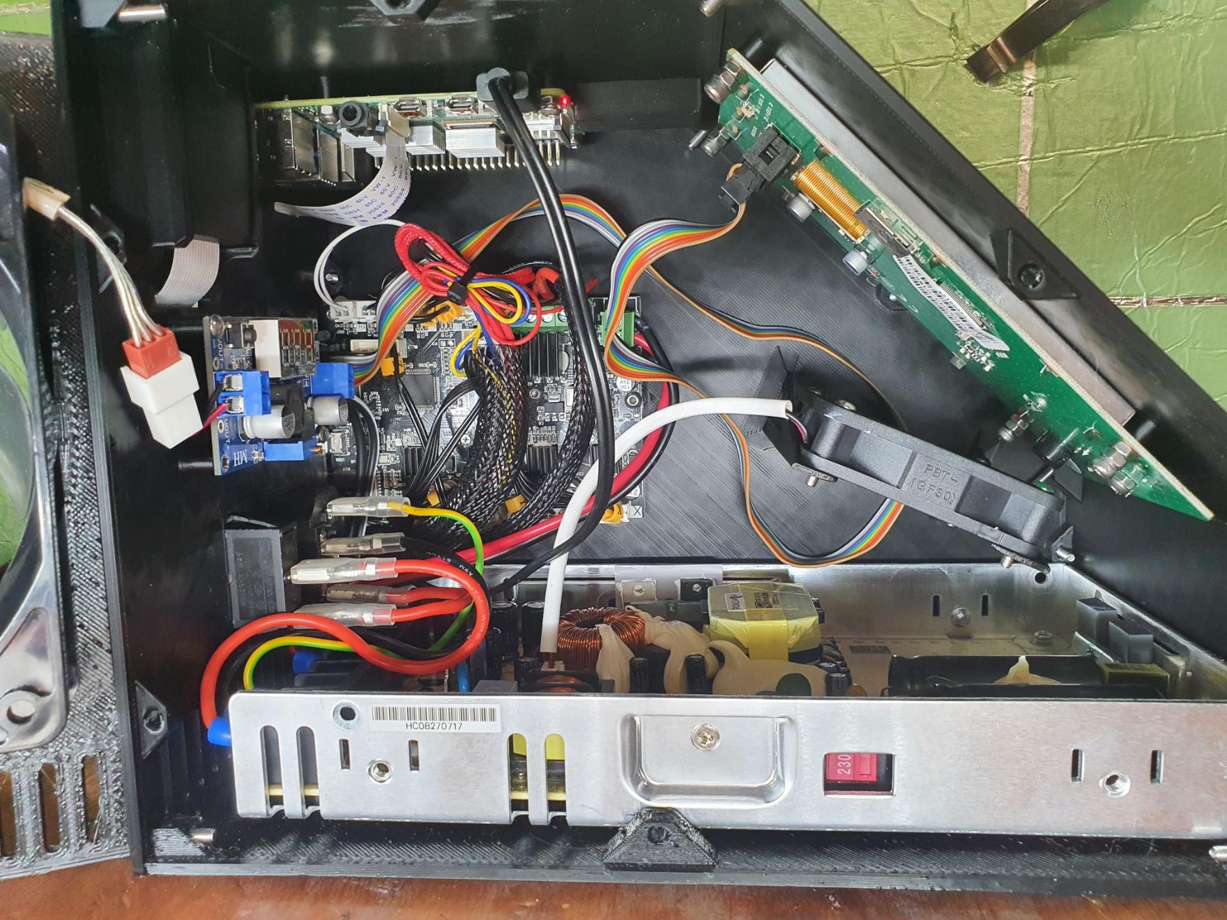
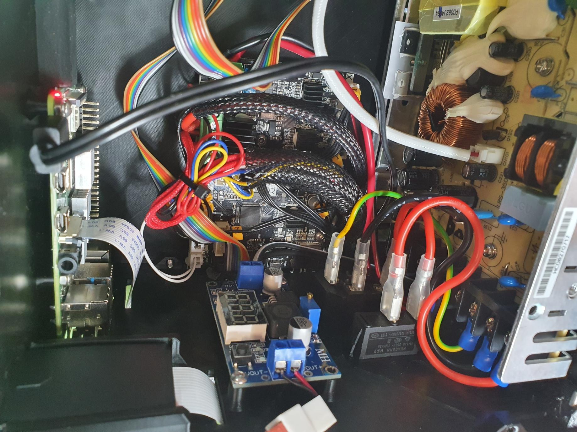
Houses the following parts:
- 4.2.2 ender board
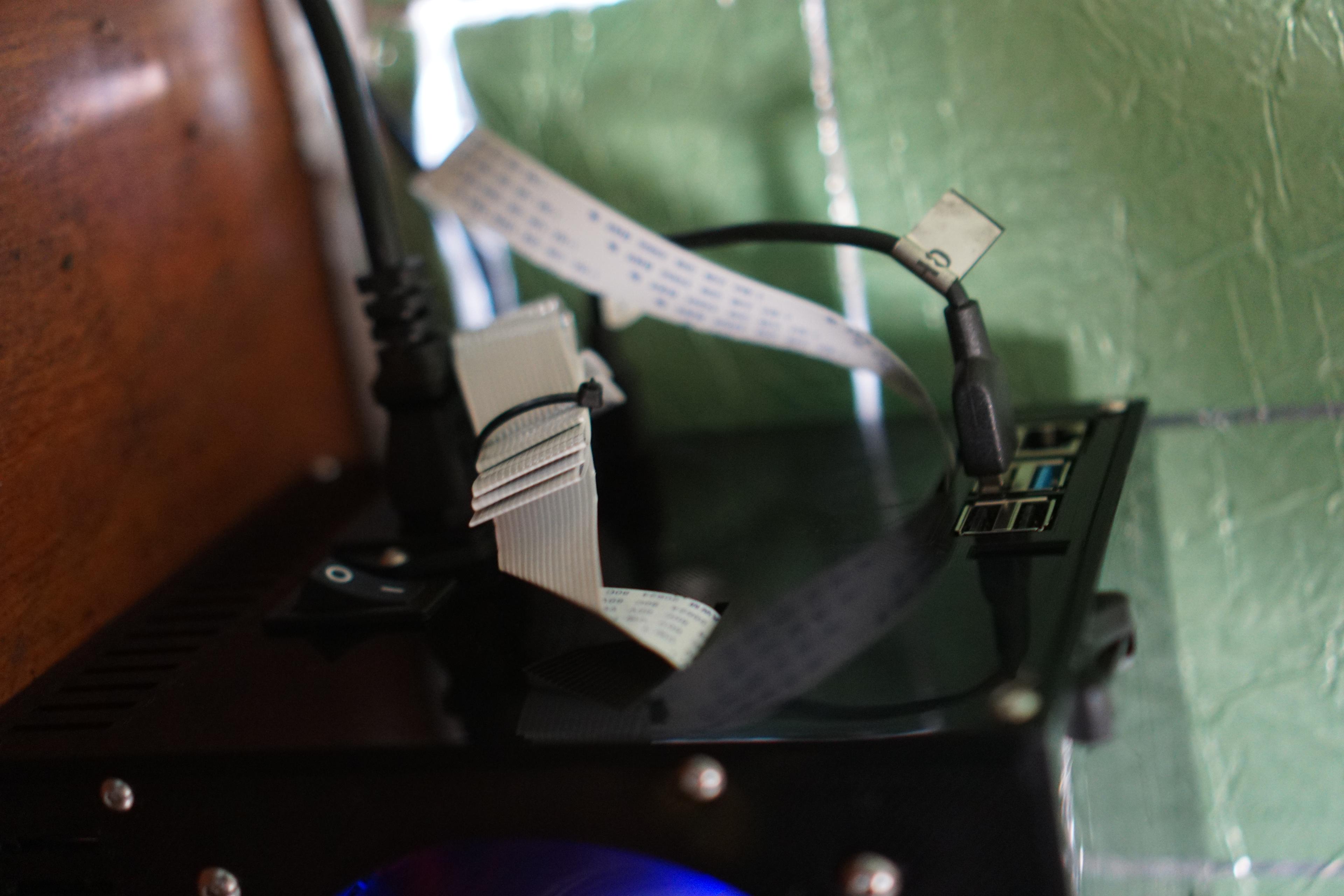
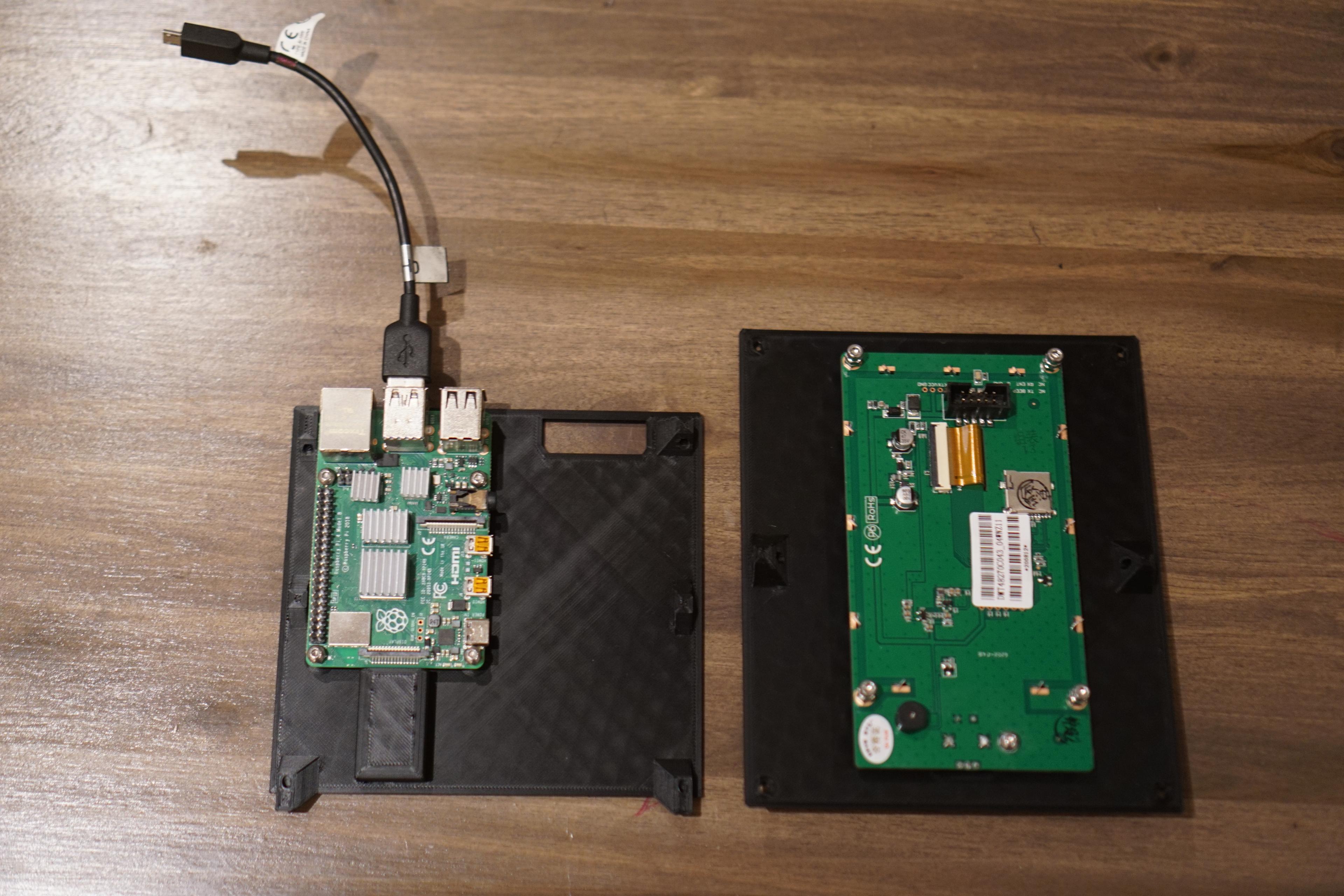
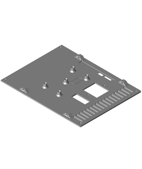
- Pi 3b / 4
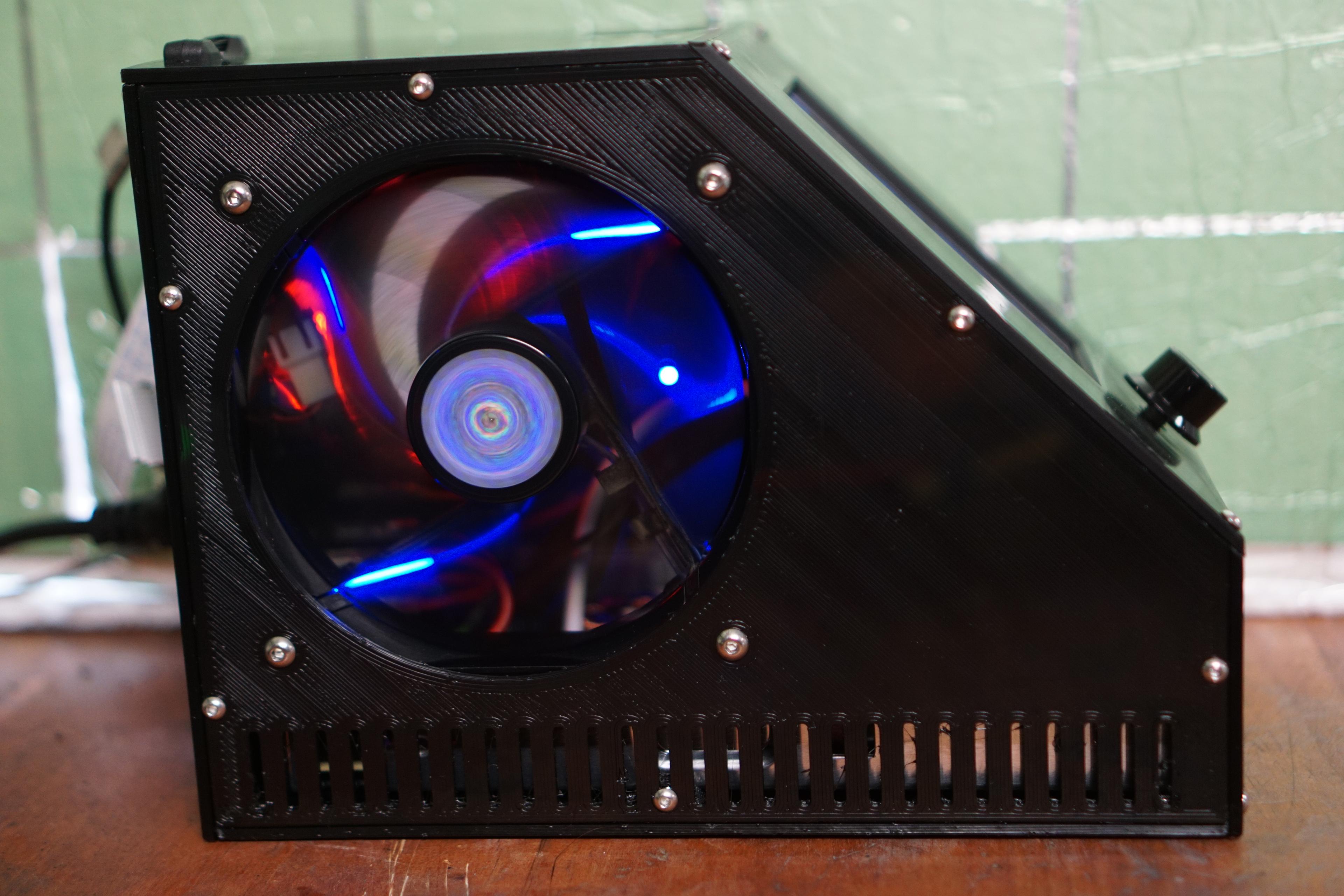
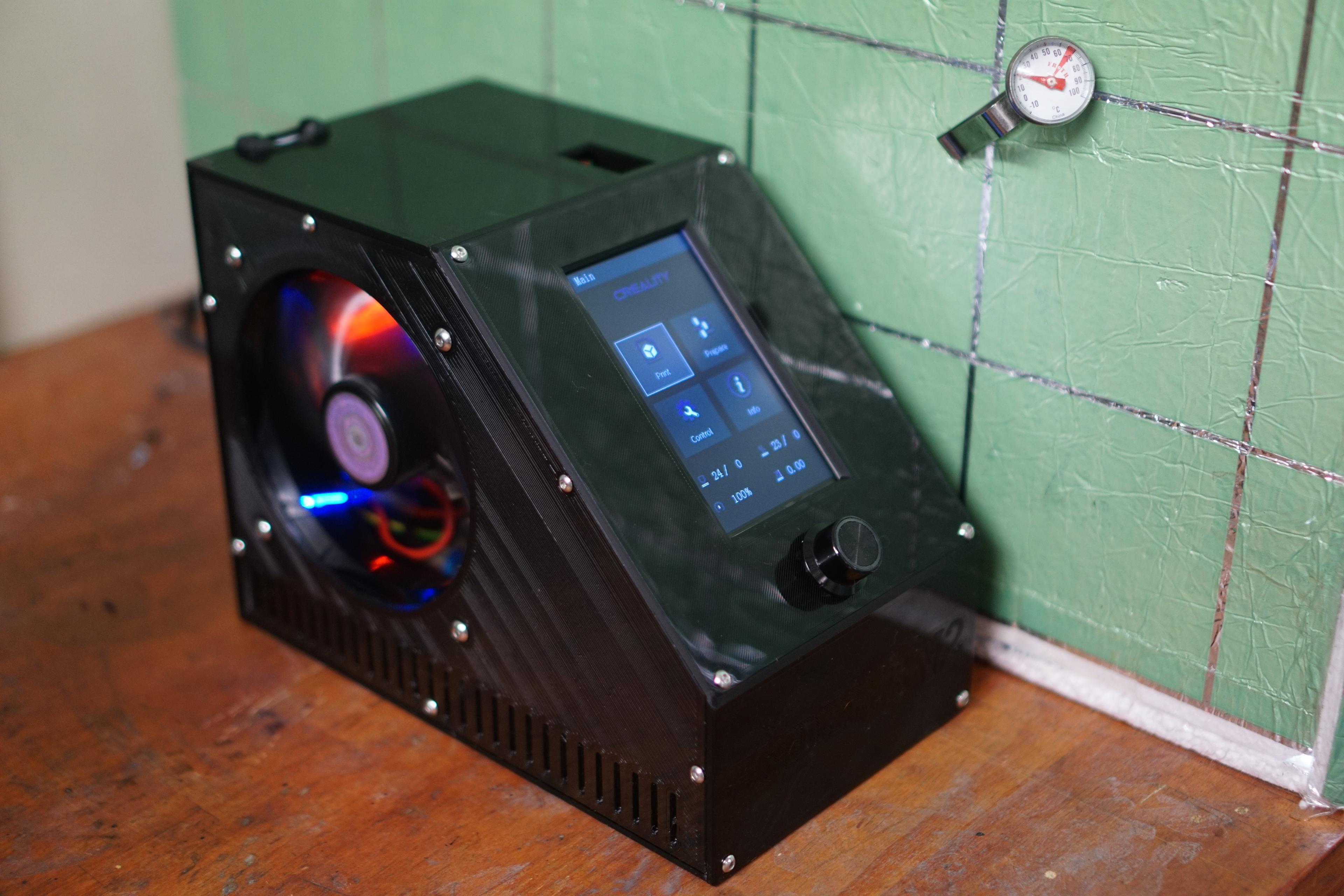
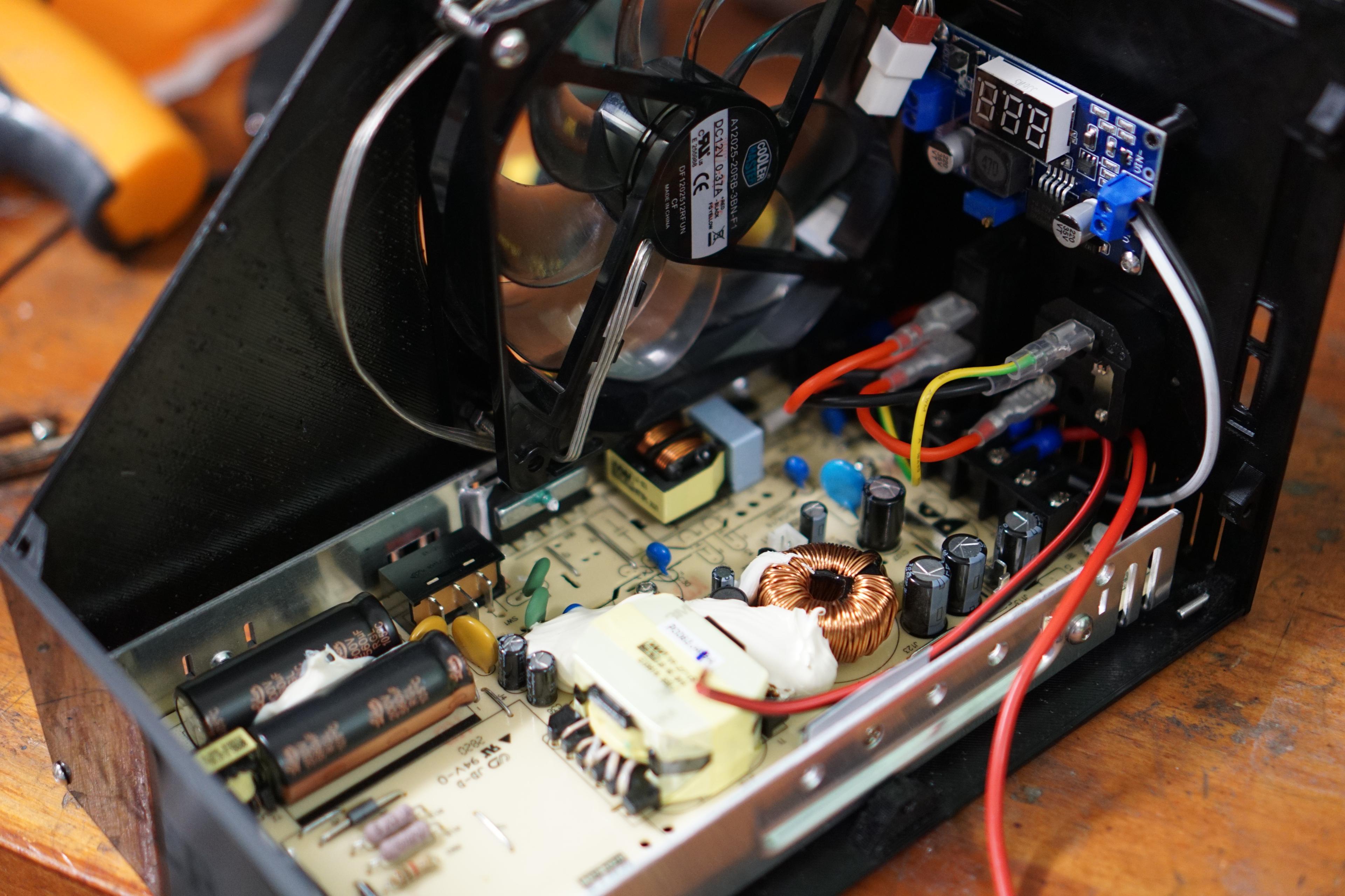
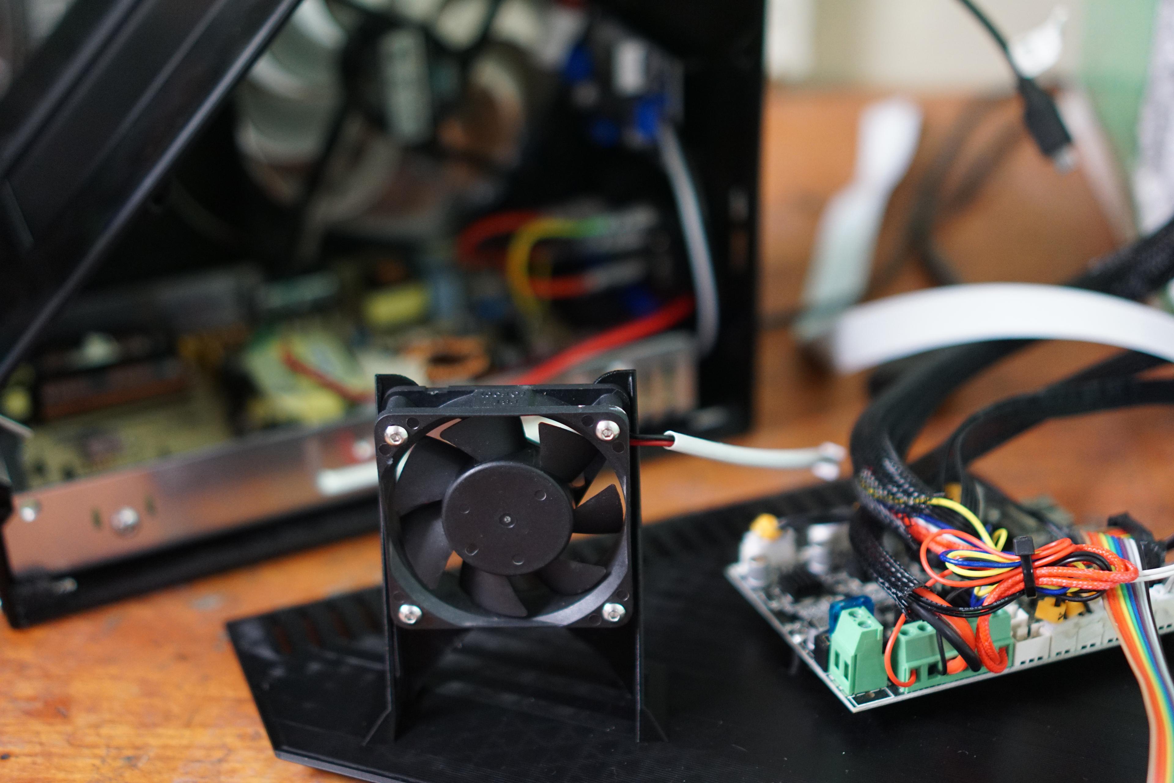
- 120mm fan
- Buck converter LM2596 LCD (big) or non-LCD (small)
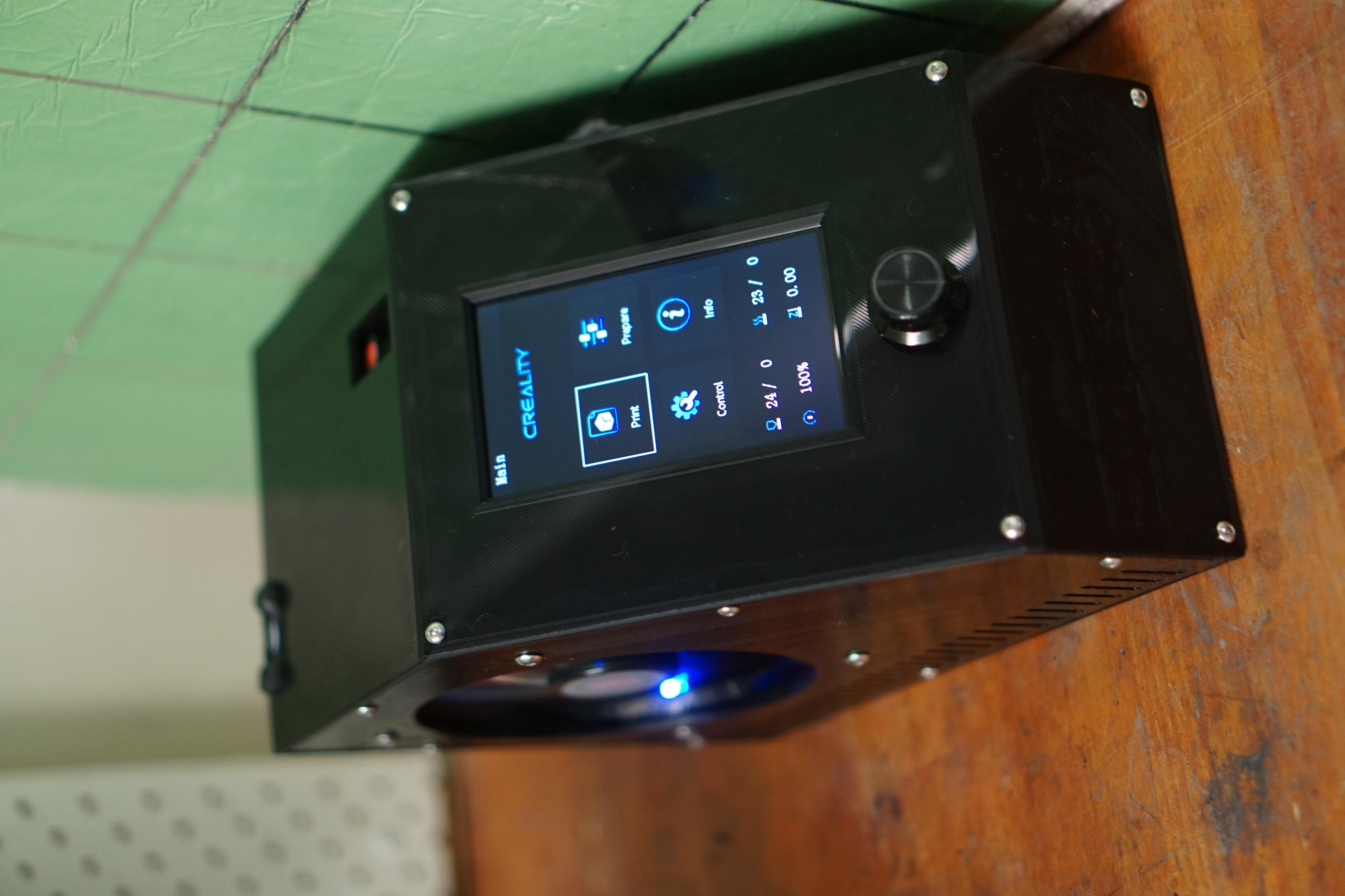
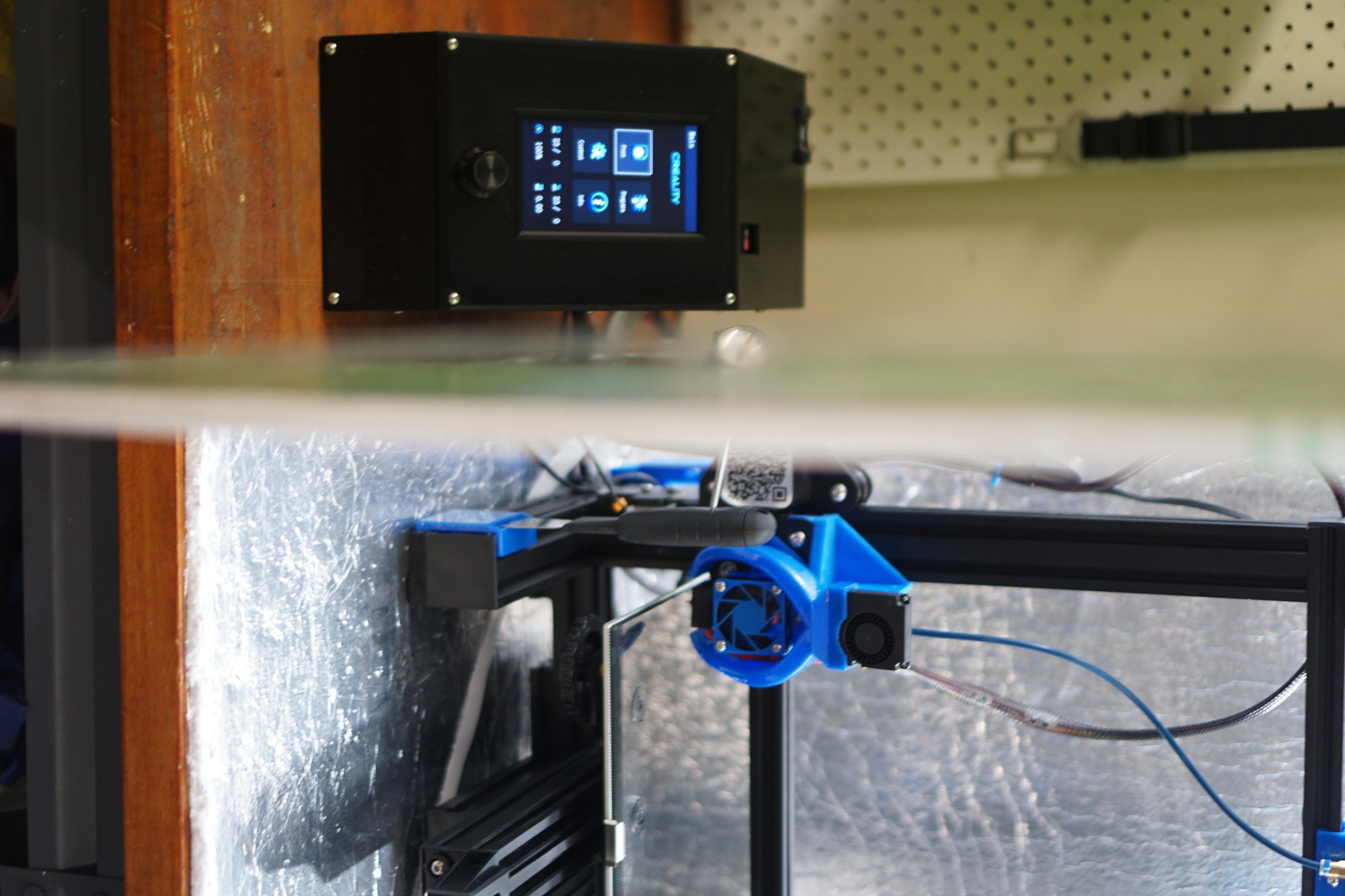
- Ender 3 v2 screen
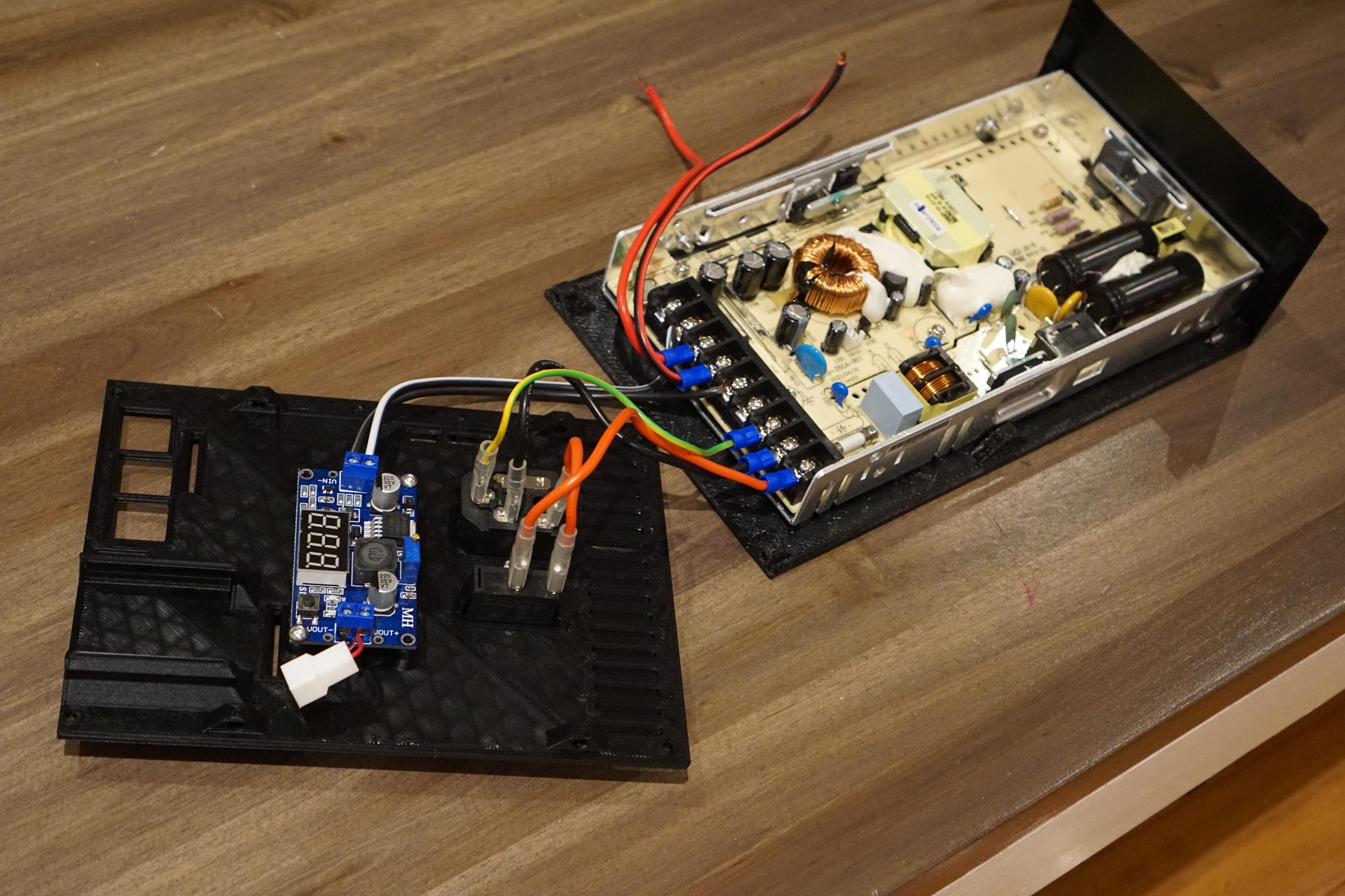
- Maxwell PSU LRS350 (stock ender 3 v2)
- SD card extender
I designed this as all my parts for my printer was all over the place as I have an enclosure for my ender to print ABS.
I added the PSU fan for a failsafe and to see what voltage I can run the 120mm fan at before the PSU fan kicks in. I’ve only run 12V so far and the PSU fan has not turned on yet, now I will try 7V to see. Will update my findings.
There are 4 locations for the buck converters: Back (recommended) Left & Right (please make sure your cables won’t touch the PSU components when it's all closed up) Top (use nuts as spacers so the screws don't bottom out, be careful when putting the left panel on as there is not much space between the fan and buck. The buck will be right in front of the Pi's power input so the cable might be a tight fit, you might need to use a 90° adapter)
Please use the Calibration print to get your flow rates to suit a M3 screw. The holes were designed 2.9mm so that's the same size as the m3 screw so you might need to have a higher flow so the screw can bite in. My calibrated flow is 87 but I printed at 95. Initial flow shouldn't matter and I kept that at 100 so there are no gaps on my bottom layer. Important note - After each panel you print check the holes with a screw again so you can compensate for it as you go.
I printed on the glass side on my bed (not textured) so the print comes up glass like on the outside.
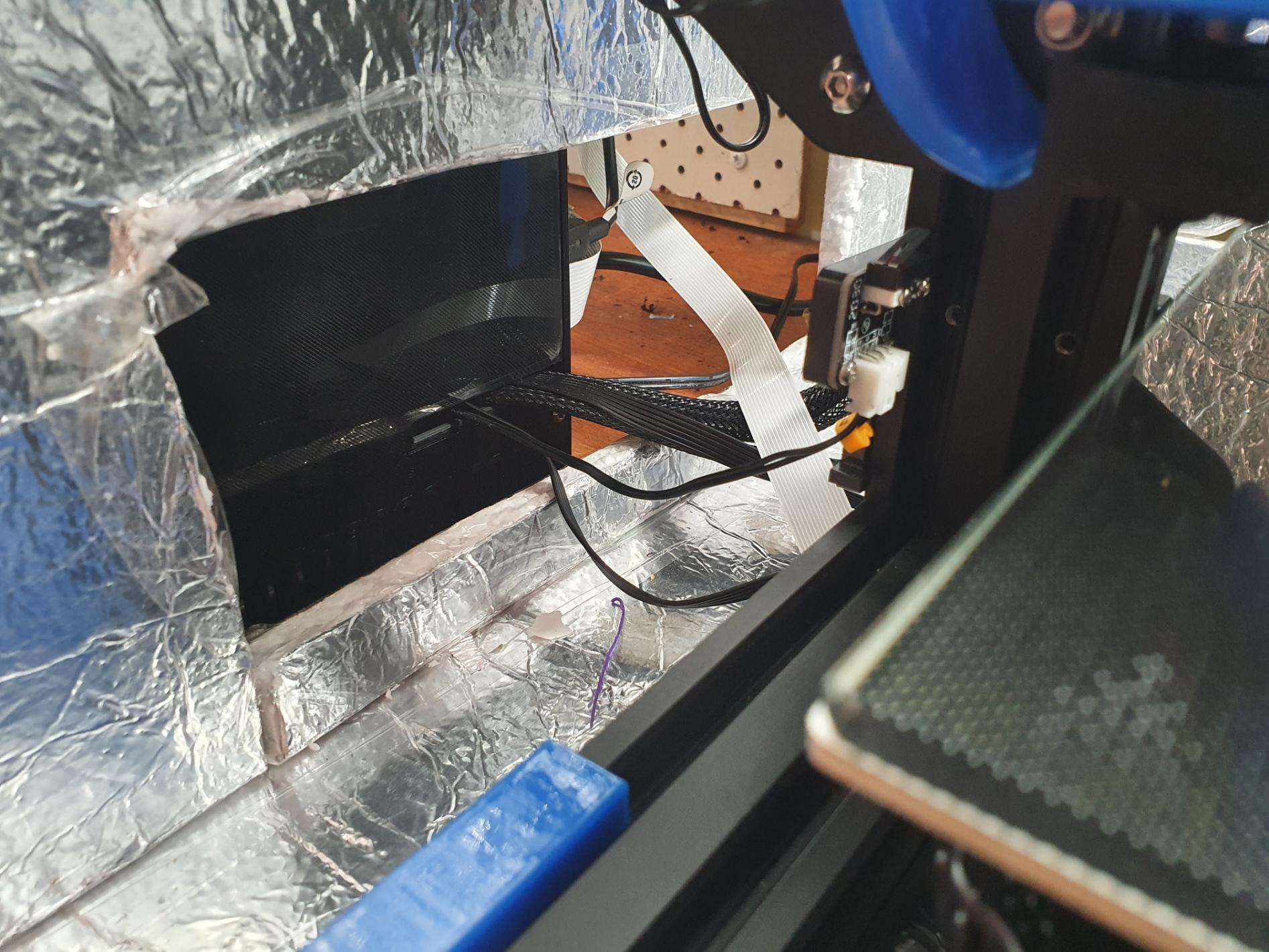
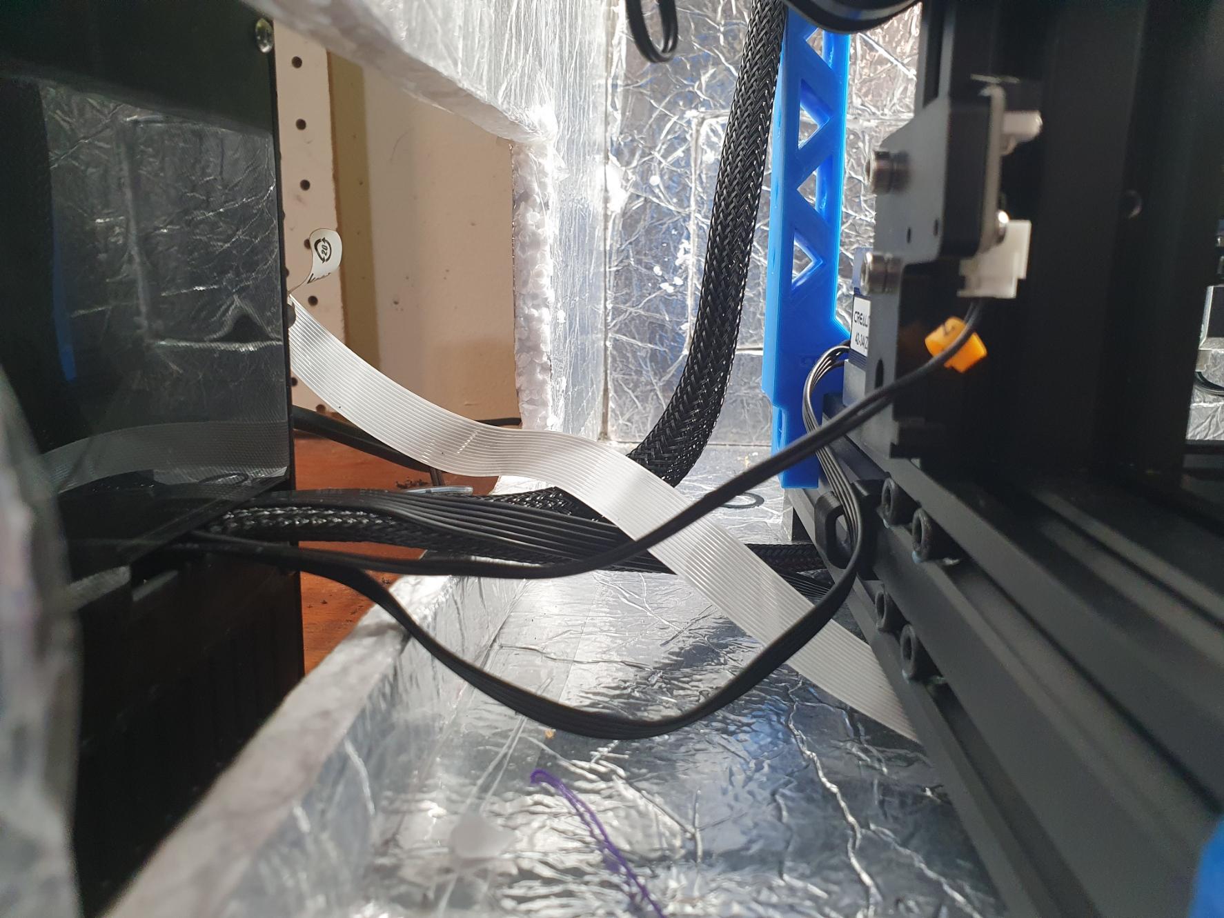
Information about assembly: -Mount the PSU to the bottom panel from underneath using the 4 original screws. -Mount the Pi to the top panel, you might need to drill out the Pi with a 3mm bit as my 2.9mm screws would not go through the board. Use a nut as a spacer when using 8mm M3 screws -Mount the screen to the face panel using the original screws and adding 2 nuts to each to make sure they don't bottom out. I added a standoff next to the button wheel as extra support that you can add the 5th screw if you wish. -Mount the buck converter on the back panel, I’ve allowed for both sizes but only tested the bigger one It would be best if you could calibrate it before you install it as doing it with the system on could lead to you accidently touching the high voltage PSU components. Install the SD card extender if you have one. -Fix the panels together expect for the right panel -If you are lazy like me, I kept call the wires connected to the motherboard and installed it onto the panel like that and then installed the internal fan with the lead exiting towards the motherboard. I used M3x20mm screws to fix the fan. you might need to disconnect the z stop switch on the printer side to give you a bit of extra slack. install the panel to the enclosure whilst keeping the wires in the slot in that cover.
The file is publicly available on Onshape for easy edits: https://cad.onshape.com/documents/ae603507a80808bfc188979a/w/2beb3a60eb3254ce11504ef4/e/9226ce472429d2bdb8b07314