
Anycubic Mega Zero Z-Axis Linear Rail
Model originally uploaded to Thingiverse at https://www.thingiverse.com/thing:4931111.
EDIT:
9/23/2021
- Added flexure lead screw bearing block alternative to the remixed bearing block. The flexure design allows room for the leadscrew tip to wobble and hopefully prevent the deflection force from translating into the x-gantry and cause z-banding patterns.
End EDIT
This mod swaps v-wheels for linear rails and supports dual lead screws. The lead screw mounts also feature a flexure design to help mitigate z-banding (modified from a design by @amtech https://www.thingiverse.com/thing:4806806
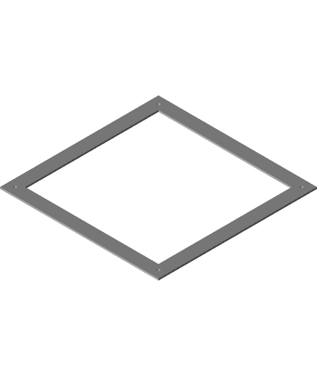
The mounting plate was remixed from https://www.thingiverse.com/thing:4804383 by @djos_1475.
I assume that you are currently using dual lead screws already and if you are not then you will need to procure a secondary leadscrew and motor as well as research hot to connect the secondary motor. I am currently using an SKR Mini MZ and it supports 2 z-axis motors connected in parallel.
This mod does not support mounting the extruder on the x-axis. You will need to remount the extruder up top by the spool holder or swap to a direct drive. The stock motor cable should be long enough to reach (at least on my machine).
I don't have the dimensions for the Anycubic Mega Zero V2 but as long as the gap between the z-plates are 27mm then this will work.
Testing comments: I've also made a mod that uses linear rods for the Z-axis (https://www.thingiverse.com/thing:4817790). There are photos with test prints comparing the two. In short, I do think the linear rail is slightly better and more consistent. I am also using TR8x2 instead of TR8x8 lead screws (stock). Wobble is much more difficult to address with TR8x2 due to the aggressive pitch. I'm pretty happy with the result. As to which you want to try? It depends on your budget.
Other remixed parts included in project: https://www.thingiverse.com/thing:4797901 NEMA motor mounts https://www.thingiverse.com/thing:3326157 Lead Screw support
BOM: (8) - M3x20mm cap head screws (For securing lead screw assembly and MGN12 mount) (8) - M3 nuts (20) - M3x6mm cap head screws (For securing MGN12 to frame and MGN12 Mount) (4) - M5x40mm button head screws (For the spacers for the outer 2 wheels on each side, 4 total). (2) - MGN12H @ 300mm linear rails (12) M3 T-Slot Nut (MGN12 Mounting - space them evenly)
Flexure Lead Screw Bearing Blocks: (2) 688zz bearings (8) M3x10mm screws - Use M3x8mm screws if you're not going to put the lid on top. (4) M4 t-nut (4) M4x30mm
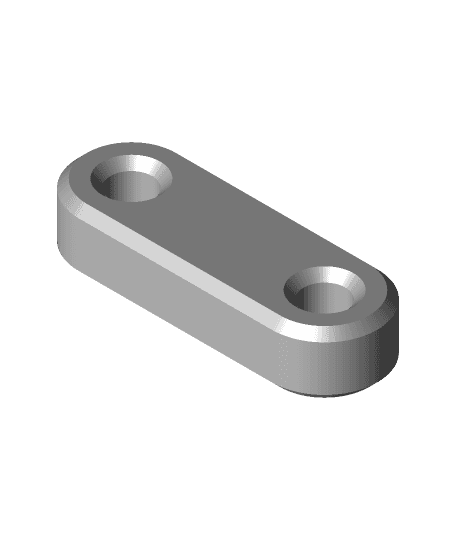
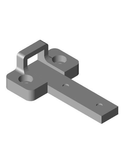
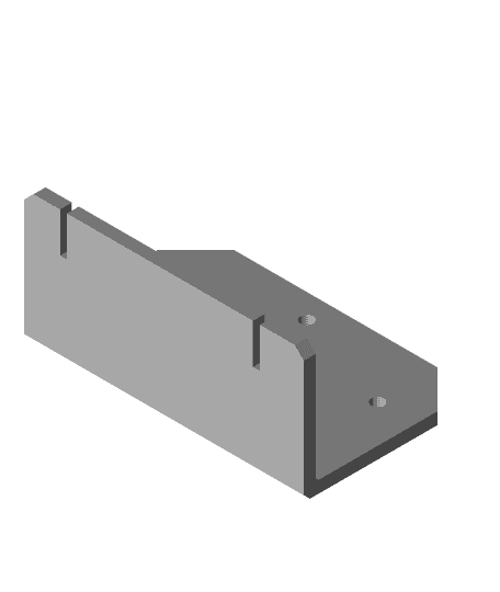
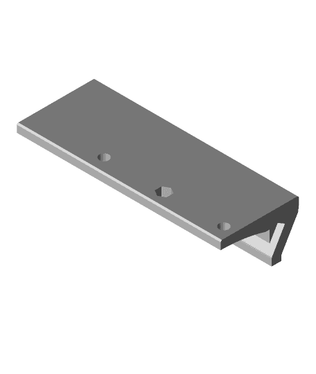
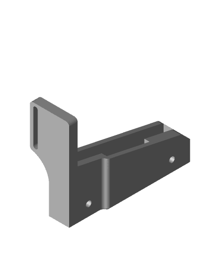
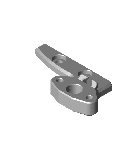
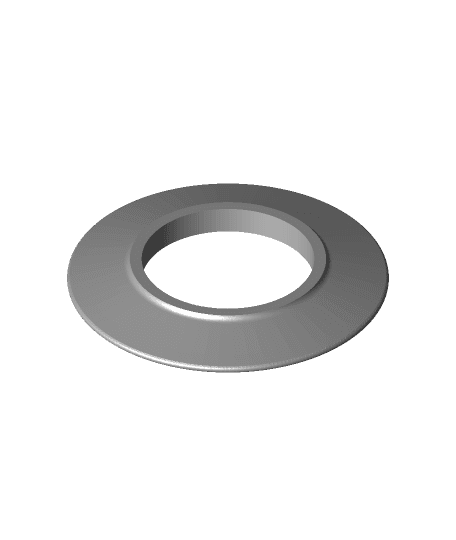
Things to print: (1) Z-Axis Linear Rail Plate - LEFT.stl (1) Z-Axis Linear Rail Plate - RIGHT.stl (2) Z-Axis Linear Rail Lead Screw Flexure.stl (2) Z-Axis Linear Rail MGN12 Block.stl (4) Z-Axis Linear Rail Spacers.stl (1) Linear_Rail_25mm_Spacer.stl (2) Motor_Mount_-_with_alignment_guide.stl
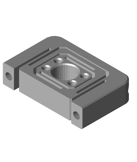
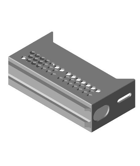
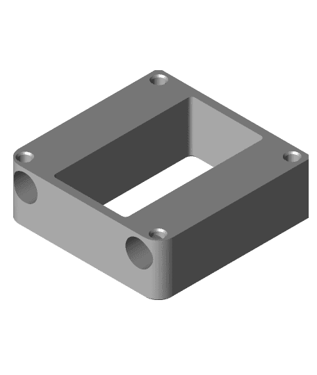
Lead Screw Bearing Blocks: (2) Top_Bearing_Block_-_with_alignment_guide.stl (2) Top_Bearing_Block_Cap.stl
OR
(2) Flexure Bearing Block Top.3mf (2) Flexure Bearing Block Base.3mf (2) Flexure Bearing Block Lid.3mf (Optional)
(2) https://www.thingiverse.com/thing:2368837 MGN12 alignment helper
All parts are to be printed in default orientation without support with 3-4 wall @ at least 30% gyroid infill. I recommend using PETG and of course PC-ABS if your printer is in an enclosure.
There is a sacrificial layer in the Z-Axis Linear Rail Plates for the M3 screws and nuts that mounts the lead screw assembly
When installing the MGN12 rail, make sure that there is a 25mm gap from the top of the Z-axis.
Installation:
- Attach the flexure lead screw assembly to the backplates using M3 nuts and M3x20mm. This needs to be done first since you will not have access to the M3 screws once the plates are mounted.
- Clean out the sacrificial layer in the Top Bearing blocks and insert M3 nuts into the slots.
- Remove your lead screw.
- Disassemble your X-axis and remove the wheels, metal spacers, eccentric nuts, and the M5 screws for the wheels.
- There are four M5 screws that are holding the metal plates to the 2020 extrusion. You will need to remove two of the inner M5 screws (one on each side) and reuse them later on the MGN12 mount block.
- Using four Z-Axis Linear Rail Spacers and four M5x40mm screws and existing M5 nylock nutes, loosely attach the back plates to the metal plates. You are replacing the two outer wheels on each side with these spacers.
- Add M3x6mm and T-nuts to the linear rails. Each rail will use six sets and you can even them out to your liking. Make sure to leave the rail lock nub so the MGN12 block doesn't fall out when mounting. You will most likely lose bearing balls if this happens. BE VERY CAREFUL WITH SUBSEQUENT STEPS.
- Place the 25mm Linear rail spacer flushed with the top of the frame and attach your MGN12 rail. Once it's attached, you can use the MGN12 alignment helper to realign the rails and tighten them. Don't over tighten since the T-nuts will bend the v-slot. Finger tight should be fine. Repeat this step for the other side.
- Remove the top 2020 extrusion and lower the loosely assembled gantry in place. Use a roll of 2-inch packaging tape support the gantry on the printer bed.
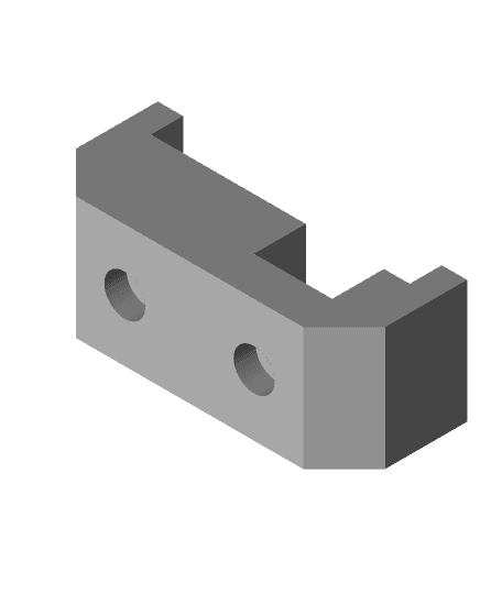
- Attach the two printed Z-Axis Linear Rail MGN12 Block to the MGN12 block using four M3x6mm screws on each side. Don't forget to add the two M3 nuts on each of these.
- Align the MGN12 block to the backplate and insert the two M3x20mm and loosely secure.
- Using the two M5 screws removed in Step 5, attach the MGN12 mounting block to the metal plate.
- Secure the rest of the screws to tighten the gantry in place.
- Reinstall the top 2020 extrusion and the Bearing block. Make sure to align the outer marker of the bearing block to the edge of the 2020 extrusion.
- Remove the old motors and install the new motor blocks and make sure to align the outer wall of the markers to the 2040 extrusion.
- Slide the gantry up and down to make sure it's smooth and does not bind. Use the MGN12 alignment helper to adjust your linear rail.
- Install your lead screw, double-check that all cables are reattached properly. Remove the stopper nubs from the linear rails. While homing, stay near the printer to turn it off at the first sign of an issue and readjust. Don't forget to calibrate your nozzle z-offset.
NOTE: 300mm MGN12 will work perfectly with this with a few millimeters to spare if aligned properly (25mm from the top). I believe (I haven't actually tested this) 350mm will work as well but space will be very tight with the print bed. You won't need to have a 25mm gap at the top with 350mm rails, but you will need to make sure that you using stock print bed dimensions.
When reinstalling your lead screw, I've found that adding a 4mm ball bearing to sit between the lead screw and motor shaft does an amazing job with flexible couplers in stopping vertical compression and wobble issues. Check out this video for more details: https://www.youtube.com/watch?v=zI-Fb8uTTKs
Anycubic Mega Zero Z-Axis Linear Rail
Anycubic Mega Zero Dual Z Linear rod swap
Anycubic Mega Zero X-Axis Linear Rail
AnyCubic Mega Zero V1 Y-Axis MGN12 Linear Rails

HMG7.2 Anycubic Mega Zero Gantry Adapter.stl
X-Axis Linear Rail For MGN12 Linear Rail
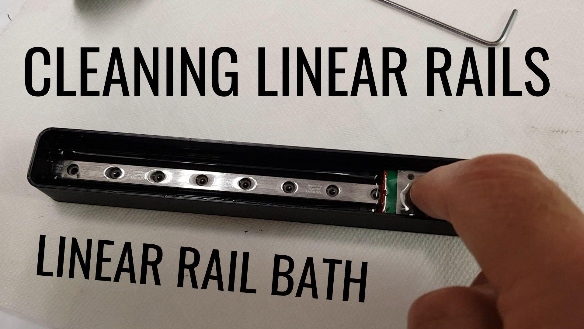
Linear Rail Bath - Clean your linear rails
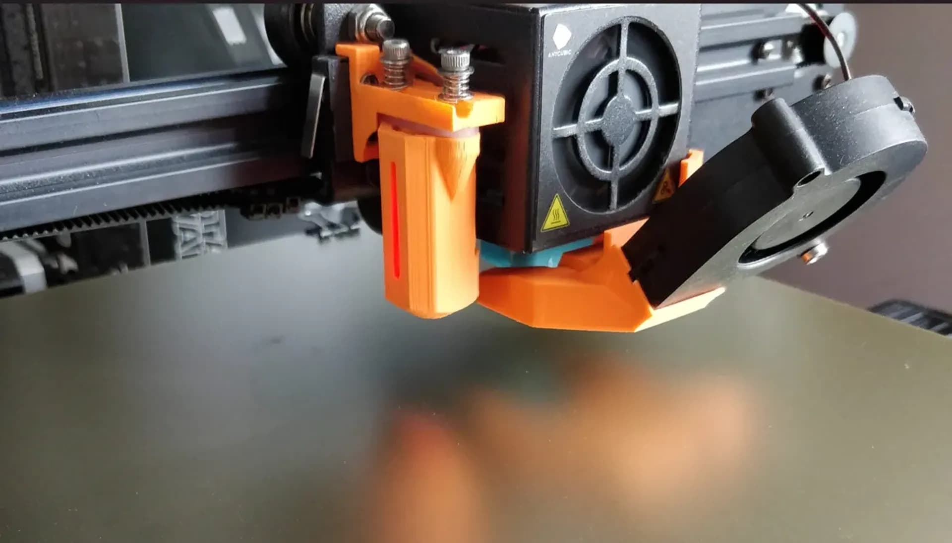
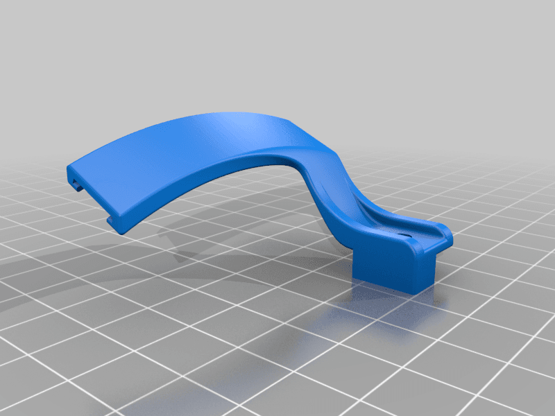
Anycubic Mega Zero 2.0 5015 cooling fan duct
ORIGINAL Anycubic Mega Zero Layer fan Funnel
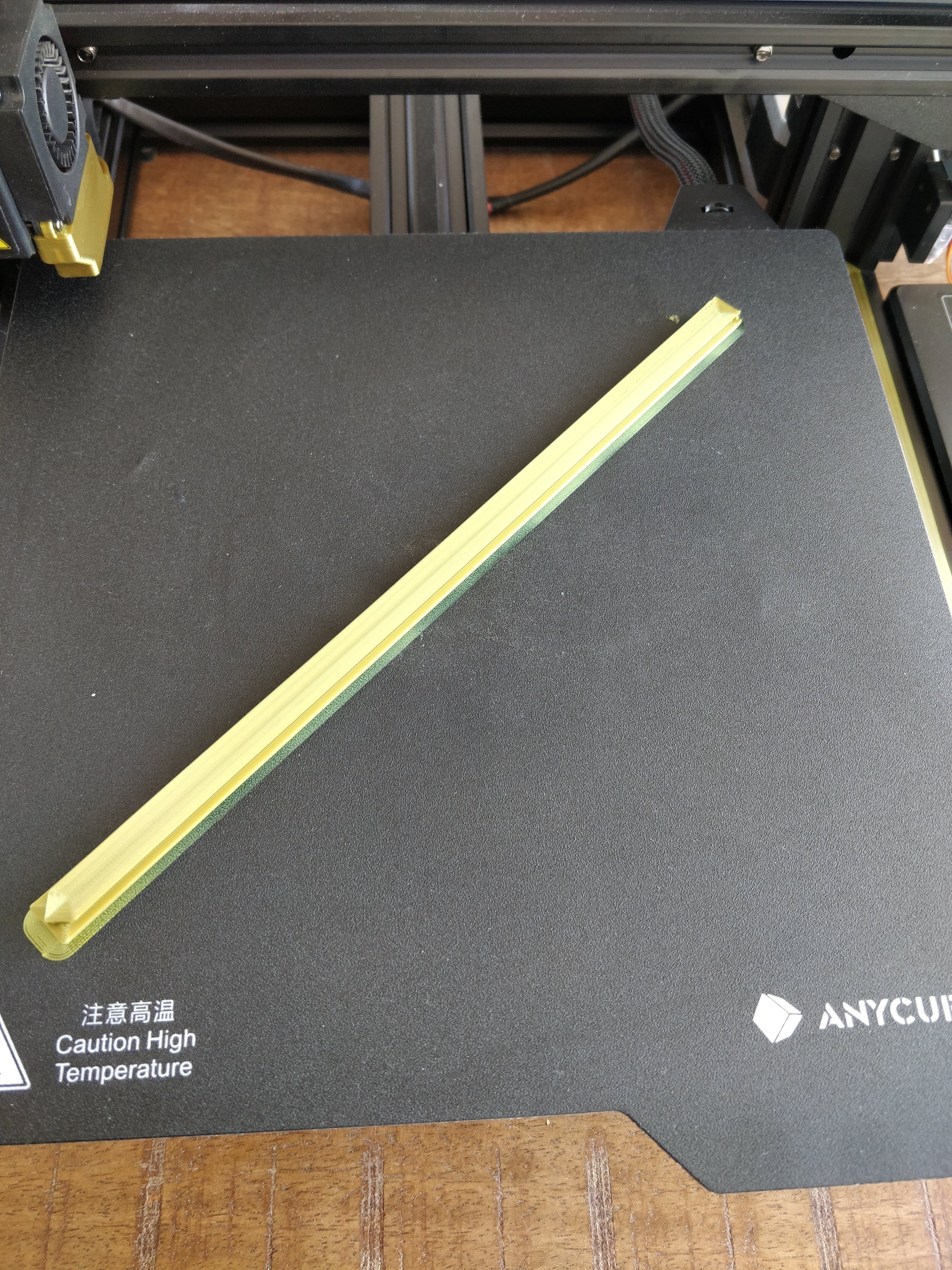
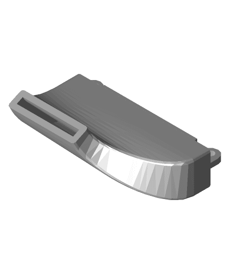
Anycubic Mega Zero 2.0 Front V-Slot Cover
Anycubic Mega Zero under bed power supply (LRS-350-24)
Creality/Ender bed screw drilling template for Anycubic Mega Zero
Anycubic Mega Zero Sherpa Mini Mount
Anycubic Mega Zero Depth Gauge
Anycubic Mega Zero Lead Screw Support Bearing Block
LED tape holder i3 Anycubic i3 Mega MK4 / LED-Band halter i3 Anycubic i3 Mega MK4
Hot End Decorative Plate for Anycubic Mega, Mega s, and others
MGN12 2040 Carriage Stop-Linear Rail Alignment Tool.stl
Ender 5 Core XY with Linear Rails MK2
Mega Zero combination filament runout and tangle sensor
.jpg&w=3840&q=75)