Anycubic Mega Zero Dual Z Linear rod swap
Model originally uploaded to Thingiverse at https://www.thingiverse.com/thing:4817790.
Check out my other design for x-axis linear rail for the Mega Zero: https://www.thingiverse.com/thing:4830265
This is part of a series of mod designs for the Mega Zero V1, here are others mods I've designed:
EDIT 4 8/9/2021 Added new design that uses a flexure lead screw nut mount created by @amtech https://www.thingiverse.com/thing:4806806. This should add built-in wobble compensation. When using this, also take a look at this video https://www.youtube.com/watch?v=zI-Fb8uTTKs. It works when used in combination with flexible or disc couplers. It will prevent slopping issues.
You will need 4 m3x20 cap head screws and 4 m3 nuts to install the flexure plates. I am currently using this right now and the result is just as good as the add-on magnetic anti-wobble solutions.
Print these parts with 3 walls and at least 30% gyroid infill. Make sure that your perimeter width setting is set to 0.45mm (this is the default on PrusaSlicer). This will result in 2 walls for the flexure arms. The original design is 0.43mm for the flexure arms and one wall is not strong enough for this mounting style.
It's very important to square your frame and mounted parts (NEMA motor and the top bearing blocks / linear rod mounts. Otherwise, this will skew the flexure alignment and render them useless.
END EDIT 4
EDIT 3: 8/5/2021 Added V4 and removed the rest of the old files. Fixed issue with lead screw nut alignment.
End EDIT 3
EDIT 2:
5/6/2021 Added LM8UU Mount V3 left and right. Lead screw nut has been moved up and space widen for compatibility with my Compact Z-Axis Magnetic anti-wobble dampener V2
If you are experiencing z-banding, consider giving this coupler a try. https://www.thingiverse.com/thing:2922542 I've had really good results with this so far and it out performs a lot of cheap coupler solutions I've tried with bent lead screws.
End EDIT 2
EDIT 1:
Added LM8UU Mount V2 Left and Right that is one piece with slots for m3 nuts and m3x12mm or zip tie. The slot should be a good fit and fasteners not really needed. I personally prefer this design over the screwed-in halves.
Print with default orientation with support touching build plate only. I recommend 70% gyroid infill for PLA.
Also updated spacing with original LM8UU mount and narrowed the LM8UU slot.
END of EDIT 1
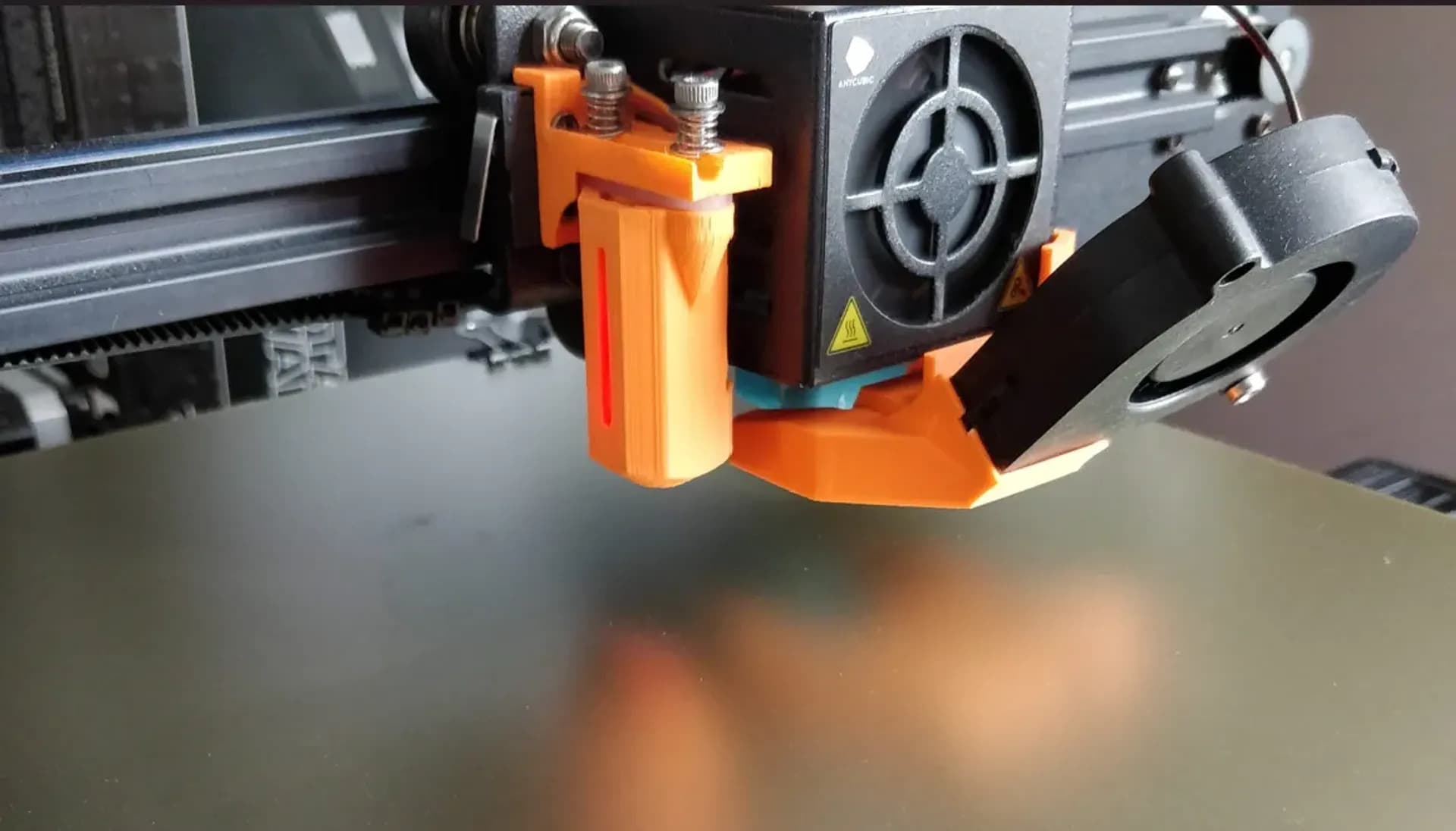
I did not include an extruder mount in the design since I am trying to reduce the weight on the gantry as well as the Z Axis. My extruder has been moved to the top using this piece: https://www.thingiverse.com/thing:3248350
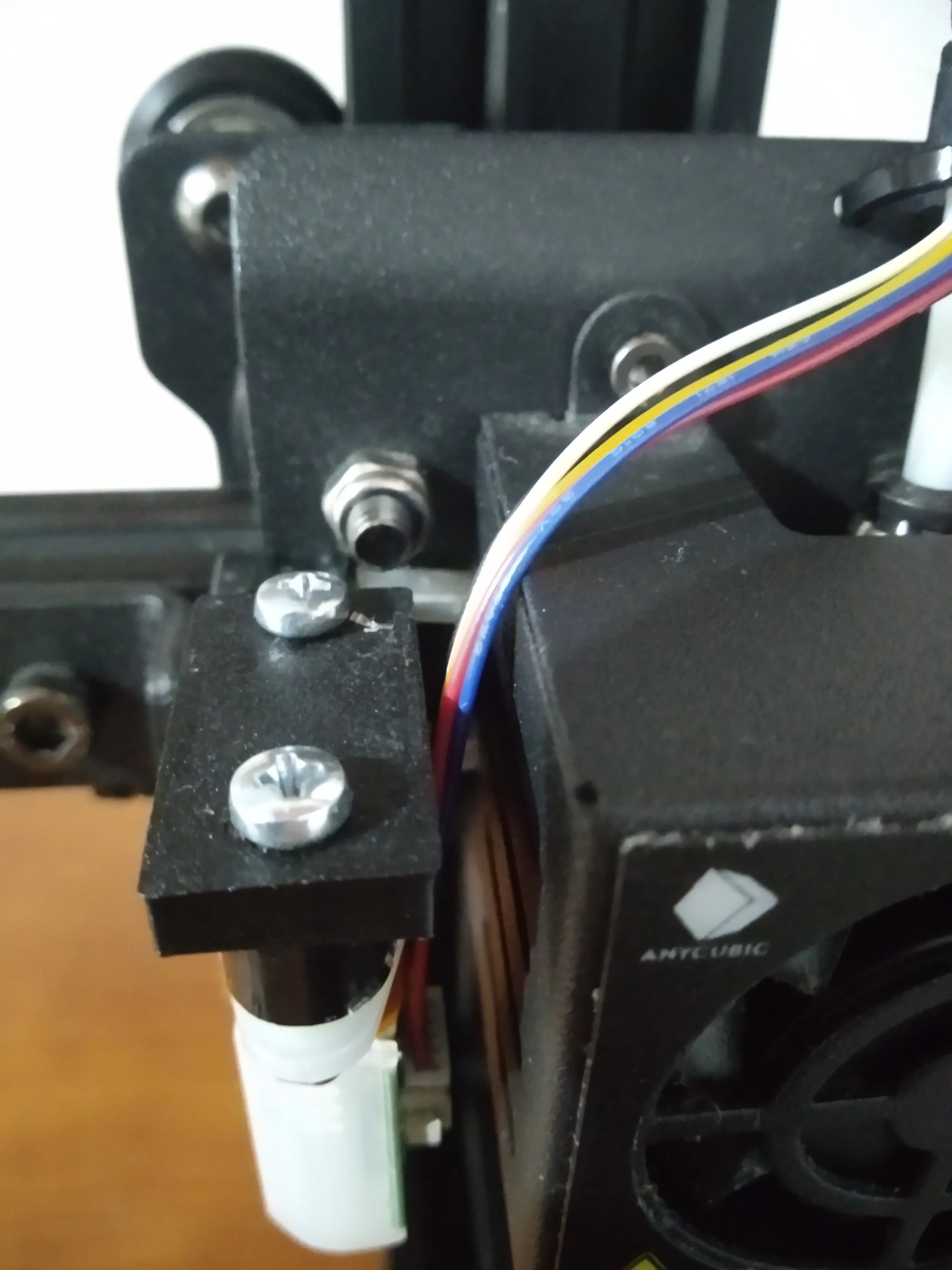
The idea behind this is to get rid of the wheels on the Mega Zero (should work with Ender 3 as well) for the Z-axis and use LM8UU bearings and rods instead. The linear rods will be sitting to the side of the motors held in place by the motor mounts and top end-caps that also provide bearing support for the lead screws should you want to take that approach. The lead screw bearings are not needed and have been known to reflect wobble into the x-axis.
Is this swap necessary? Definitely not if you're happy with the current print quality. Personally, I really hate the eccentric nut adjustment, and also the wheels are fairly expensive compared to LM8UU or Drylin linear guides. At least in my case, when adjusting the eccentric nuts, I see it move the z-plate and the lead screw along with it. After swapping to this mod, I do notice a benefit to using TR8x2 instead of TR8x8. Prior with v-wheels and TR8x2, it was still difficult to get an accurate z-offset value. I think the v-wheels were not translating the micro-movements of the TRx2.
If you do not want to replace both sides, I do think it's worth printing for the non-extruder (right) side if you're only using one lead screw. With the wheel setup and just one leadscrew, there's a movement lag on the right side when the gantry moves up and down. The linear rod should allow for more responsive movement with less friction (in theory).
All parts were made by remixing a few items:
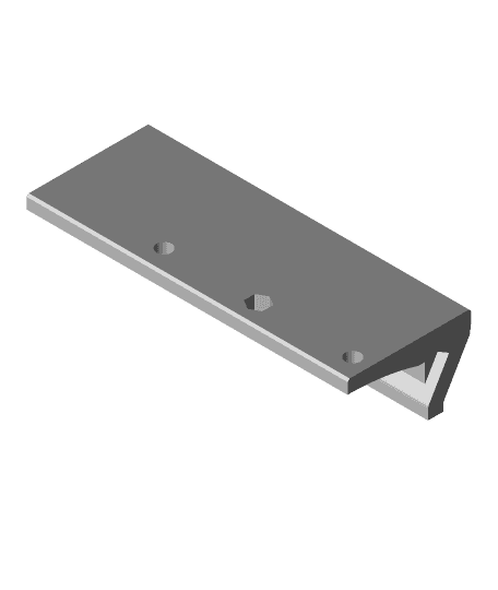
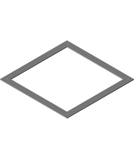
- The frame mount base plate https://www.thingiverse.com/thing:4804383 by @djos_1475. I used the based plate shape.
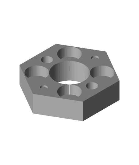
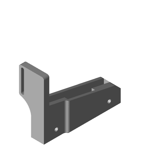
- The motor mount uses @djos_1475's https://www.thingiverse.com/thing:4797901. The center hole has been widen a bit more to make sure that any thick couplers will have clearance.
- The top mount / bearing block was remixed from https://www.thingiverse.com/thing:3326157
Dimensions: The lead screw and linear rods are parallel and 30mm from center to center. The lead screw nut mount is 12.25mm from the edge of the base, which puts the lead screw 13.50mm from the edge (edge to edge). The wheel spacer is 27mm, which means that there is a 3.5mm gap from the fame to the base of the z mounting plate (17mm from the edge of the frame to the edge of the lead screw, 21mm if we're measuring from the edge of the frame to the middle of the lead screw). The motor mount has the motor sitting flushed with the frame so it's 21mm to the center of the motor and should match with the lead screw.
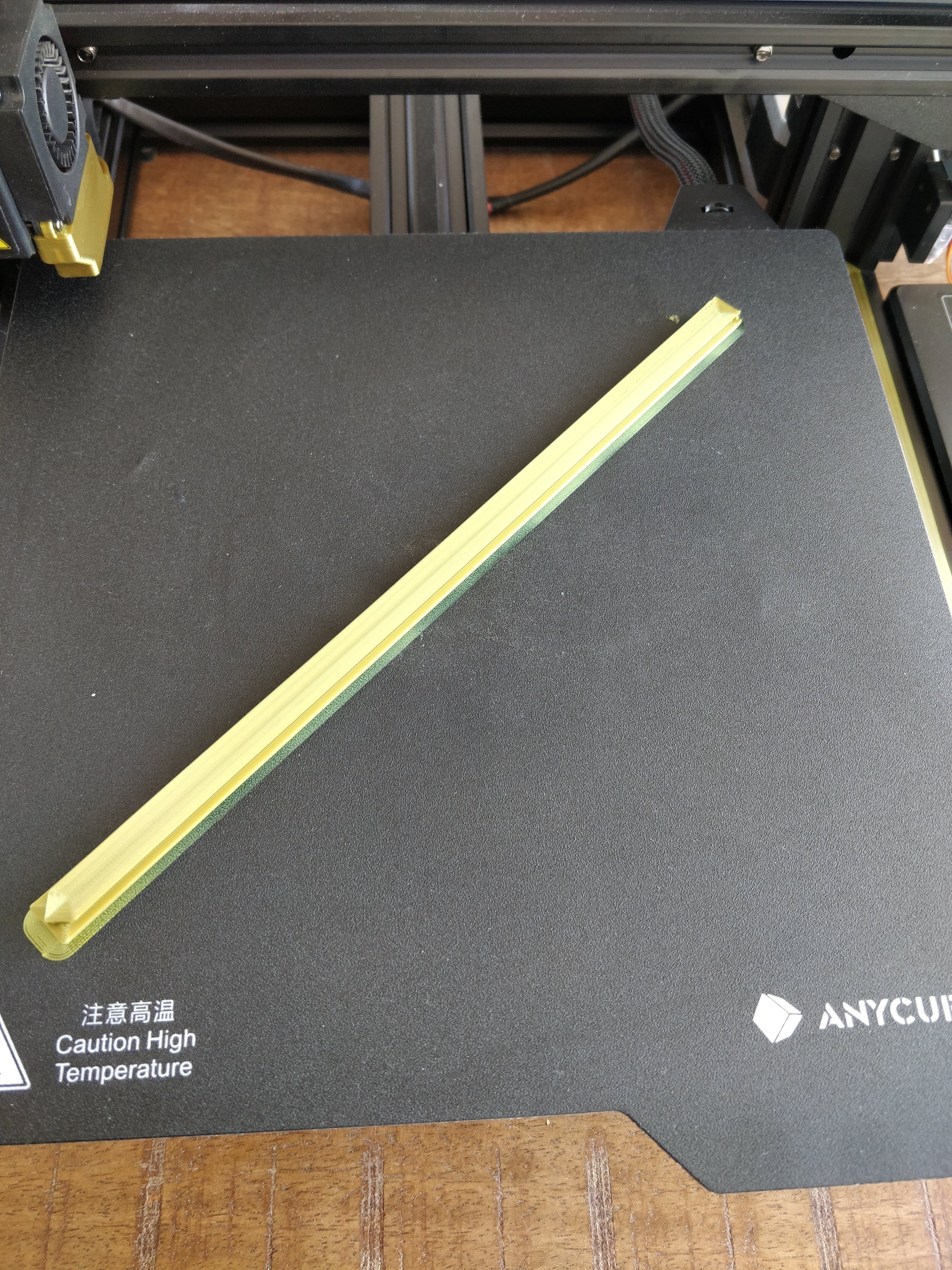
You will need the following parts: 2x 380mmx8mm linear rod. I would not go shorter than 380mm.
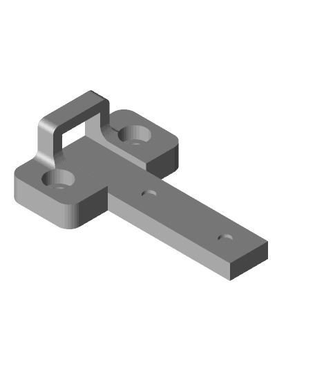
Frame mount: 4x M3x6, 8 max - LM8UU Mount 2x M3x10 or 12mm for leadscrew nut
Above screws are not necessary when using V2 plates. The fit should be sign enough to hold the linear bearings in place.
4x LM8UU or Drylin RJ4JP-01-08 3x M5x40 for the non-extruder side since the spacer is 27mm to match the extruder side.
40% support infill should be fine. I recommend 70% gyroid for rigidity.
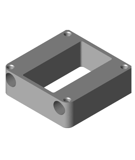
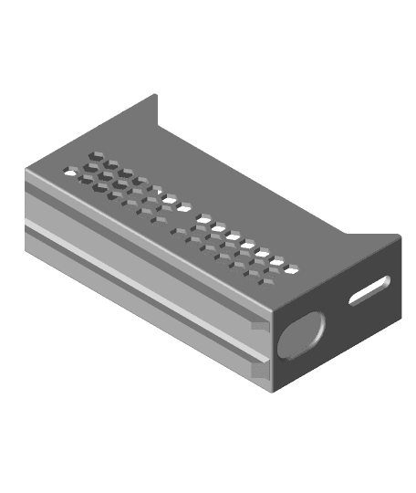
Top Mount and bearing block (optional parts are needed if you want it secure lead screw): 2x 688ZZ bearing - optional 2x M5x20 bolt (M4 Works) 2x M5 T-nut (M4 Works) 4x M3x8 - optional (4x M3 nut as well) 1x M3x6 1x M3 nuts
Motor mount: 1x M3x6 1x M3 Nut 2x M3x16 2x M3x8
40% support infill should be fine. I recommend 70% gyroid for rigidity.
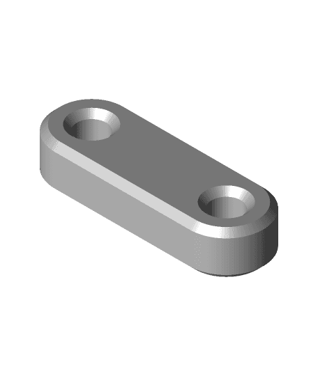
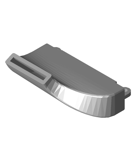
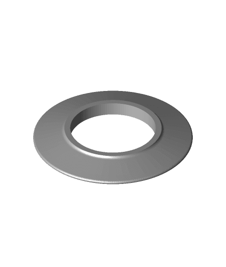
Spacer These are 27mm in length (for Mega Zero) and should match the current setup with the two 8mm spacers and wheel. You'll need to print 6. I recommend 50% or higher infill. You will need 3 new M5x40mm screws as mentioned above for the frame mount. Reuse the nylock nuts. These spacers are extra thick 14mm in diameter to sit over the groove created by the eccentric nut (that thing usually digs into the aluminum plate).
Secondary lead screw I swapped from using TR8x8 to TR8x2 and buying two new Nema 17 motors. The stepper wires are in parallel so you will need to increase the current for the z-stepper in Marlin. I am using SKR Mini MZ and the board has TMC2209 which has a peak of 2A. I am currently using 1.6A and each motor should be receiving 800mA.
Moving to TR8x2 will require a decrease in feed rate as the motor will need to do more work per revolution (from 400 to 1600 steps per rev from TR8x8 to TR8x2). You will need to decrease speed in order to maintain torque, or else you will experience slipping. Additionally, dual z-lead screws will require better couplers. A lot of people opt for flexible spider (aka jaw) couplers but I found that there is a lot of low quality sold on amazon and the good to great quality couplers are extremely expensive and harder to find. I have tested several solutions and helical and disc couplers should be avoided. While these are flexible, they also allow for compression which can cause slops and z-lag. What this means is that when the printer makes small movements upward or downward during a z-hop, one side could move more than the other. It really comes down to even friction (or lack there of) on both linear rods. This would be a problem with linear rails as well as you will have one side bind (I may be wrong but with the tight tolerance of linear rails, this would be more apparent). Spider, oldham, and solid couplers work well as there is no compression in the vertical position while allowing for lateral movement. I am currently using these 3d printed couplers: https://www.thingiverse.com/thing:2922542 which yield amazing results for being low cost and easily sourced. You should print these first and try them out before buying other couplers. It's also a good idea to shop around for quality lead screws as the cheap ones on Amazon and Aliexpress create a lot of headaches (not that their aren't good ones available for competitive prices, you might need to test out several). Good couplers really do compensate for this.
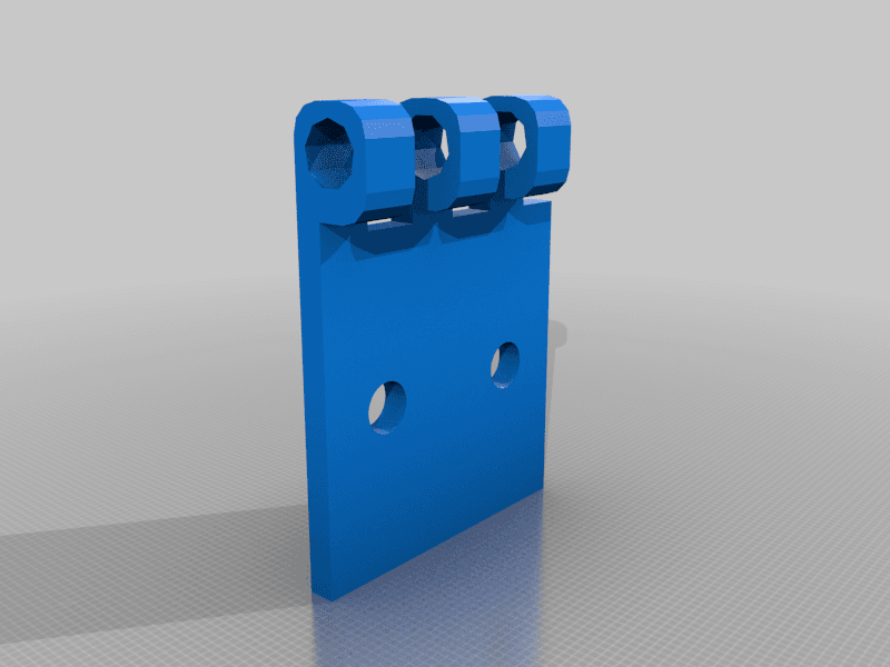
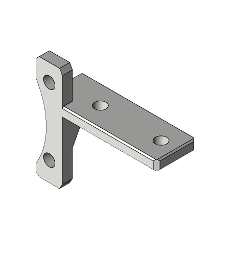
Alignment guide
The motor mounts and bearing blocks have two notches on top. These notches are 40mm apart (outer edge of one to the outer edge of the other). Use this to align the motor mount and bearing block to match the Z-pillars.
Anycubic Mega Zero Dual Z Linear rod swap
Anycubic Mega Zero X-Axis Linear Rail
AnyCubic Mega Zero V1 Y-Axis MGN12 Linear Rails
Anycubic Mega Zero Z-Axis Linear Rail
Anycubic Mega Zero Sherpa Mini Mount
Compact Z-Axis Magnetic Wobble Dampener
Anycubic Mega Zero 2.0 5015 cooling fan duct
ORIGINAL Anycubic Mega Zero Layer fan Funnel
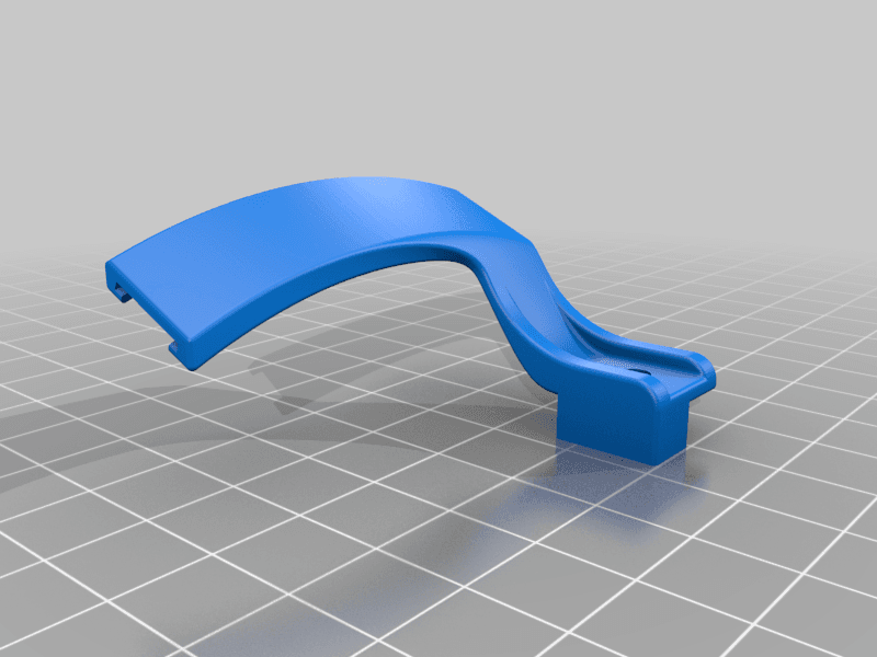
Anycubic Mega Zero 2.0 Front V-Slot Cover
Anycubic Mega Zero under bed power supply (LRS-350-24)
Creality/Ender bed screw drilling template for Anycubic Mega Zero
Anycubic Mega Zero Depth Gauge

HMG7.2 Anycubic Mega Zero Gantry Adapter.stl

Anycubic Mega Zero Lead Screw Support Bearing Block
LED tape holder i3 Anycubic i3 Mega MK4 / LED-Band halter i3 Anycubic i3 Mega MK4
Hot End Decorative Plate for Anycubic Mega, Mega s, and others
Mega Zero combination filament runout and tangle sensor
Anycubic Mega SE/Zero webcam mount
HI-flow Extruder-Head For ANYCUBIC MEGA-X with BLToutch_rimix
LED-Beleuchtung Anycubic Mega X