Model originally uploaded to Thingiverse at https://www.thingiverse.com/thing:4932174.
Updates:
2021-08-17 Added E3D_V6_Threaded_v2.stl which includes a hole to allow an M3 screw or grub bolt to hold the mount in position. Care should be taken when tightening to avoid damaging the heatsink thread, or to strip the grip from the mount material.
2021-08-15 Updated E3D_V6_Threaded.stl for better height adjustment, otherwise the official fan duct is too high
This is my take on mounting options for the official E3D V6 all metal hotend on the Creality CR-6 SE (and other models that use the same hotend).
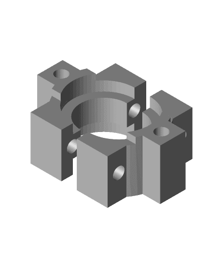
There is a mount system for the Grooved mount used by any V6 hotend, plus a mount for the threaded E3D V6 heatsink.
The E3D V6 threaded mount is much preferred as it keeps the hotend assembly to the same height as the official one.
Threaded Mount:For the threaded V6 mount you only need the E3D_V6_Threaded.stl. It is designed to match the height of the standard CR-6 SE hotend, so you can use the same fans and part cooling fan duct.
All that needs doing after building your hotend is to screw this on the top all the way down.
It's tight, so you may need something to grip the heatsink as you screw it on.
Additional hardware:
2 * M3x8 screws
Grooved Mount:For the grooved mount, you will likely need all of the "Grooved" stl files.
Also provided is a replacement optical end-stop to cater for the longer hotend. You may not need this but it will ensure the hotend does not crash into the bed. This should be tested to ensure the optical sensor is triggered before the nozzle touches the bed. You can do this with the printer on and the stepper motors disengaged, then slowly lower the gantry to check the optical sensor is triggered.
I've also included a fan duct that I put together to cater for the lower nozzle tip. Better fan ducts exist that you could modify to fit, but the one included here is functional.
Additional hardware:
4 * M3x16 screws
Both Mounts:For both mount systems, you will need to do the following after fitting:
. Perform a PID tune. This is easily done through the Community Firmware . Hot tighten the nozzle . Re-home and recalibrate your z-offset . Reduce retraction distance to 3mm or less if fitting an all metal hotend
Though the z-offset may not change much, it's still best to do it to avoid drilling the nozzle into the bed!
If the strain gauge (blue light) stays on after fitting, check that nothing is interfering with the hotend (e.q. stretched or caught wires). If it remains on, you will probably have to tune the strain gauge using the pot on the daughter board on the hotend assembly to cater for the different weight.
The grooved mount should work with other hotends with the same mount, such as the Phaetus Dragon and Dragonfly hotends, as well as others from Trianglelab, etc. However, I've not tested any of these.
All of the parts can be printed without supports with the orientation in the STL's, but the fan duct will turn out neater if you add supports touching base plate only.
The mounts can be printed using PLA as it should never get that hot at the top. The fan duct will need to be PETG/ABS or ASA to prevent warping. The optical end stop can be printed from PLA, etc.
If you use the full size V6 heater block you will need to rotate it 180 degrees for the official hotend cover to fit properly.