


Taz 5 SKR 1.4 / TFT35 Electronics Enclosure w/ LM2596 and Relay Mounting
Model originally uploaded to Thingiverse at https://www.thingiverse.com/thing:4354523.
Updates-
7/25/2020: Added version for 25A Aliexpress MOSFET by request, dimensions for ~ 42mm X 52mm between 3mm mounting holes. To make room I had to remove provisions for the relay. For this version you need to print the version of the cover WITHOUT SSR
-
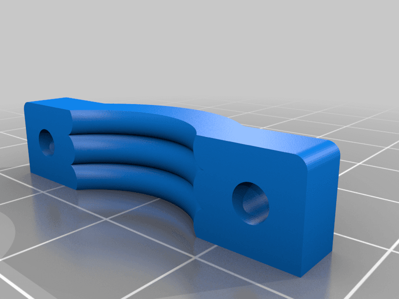
5/22/2020: Uploaded Axis Clamps Less Wires.stl for holes like for the bed where there aren't so many wires so they're clamped securely in place. Also added another with even more meat to it just in case as well as a boot meant to be printed in TPU (named TPU Boot.stl)
This is meant as an electronics enclosure for my Taz 5 32 bit upgrade to a BTT SKR 1.4 Turbo, it uses the original connector from the power supply and the original power switch and that's about it. To do this upgrade you'll need to change out the connectors on the board side to adapt the wiring to the standard RAMPS-style JST-XHP 4-pin for the steppers and 2-pin for fans and thermistors. I made a more detailed write-up on my GitHub pages over here which I'll transfer over here when I have the time.
To avoid putting stress on the SKR's onboard MOSFET I chose to go with an Auber 100A DC-DC Low On-Resistance Solid State Relay as well as a 25A External Heatsink. I did this so I could easily change it out to an AC SSR for when I change the bed heater over to 120v. For the brave amongst us you can use the onboard or an external mosfet, I provided an additional STL without the cutouts for the SSR as well.
I realize this is a lot of work to upgrade a Taz to a 32 bit mainboard / silent stepper drivers, but the cost of everything including the board, drivers, TFT35 v3 touchscreen is much cheaper than the Archim direct RAMBO replacement board. This was a project of necessity as my RAMBO was starting to act up, the motors were doing weird things and the connectors for the X axis stepper was starting to heat up so a complete rewire/revamp was in the cards for me.
This project is the result of about a month of planning and 3D modeling just about everyday after a hard days' work in NYC between printing face shields and drinking lots of coffee. So if this helps you out please consider hitting that tip button to help recoup some of my coffee / filament cost :)
Progress To-Do- Re-design back section for TFT35 v3 from the design I made for the Sidewinder X-1 to mount in the Taz 5's current LCD position.
- This is a work in progress, I haven't gotten all the wiring and electronics done yet. I believe the firmware is almost complete but not yet tested. That can be found in its current state on this GitHub fork.
- I printed the first iteration which took around 6 hours, put the heatsets in and found that the standoffs melted a little so I added chamfers around them to prevent this as well as additional cutouts to make accessing the mainboard screws easier.
- Heatset Inserts:
- M2 x 24
- M3 x 4
- M5 x 4
- Screws:
- 4x M5 (reuse from Taz)
- 4x M3 x 5-10mm
- M2 90° Countersunk Head:
- 16x M2 x 6-10mm
- 8x M2 x 12-22mm
- 6x M4 (if using SSR, comes with Heatsink)
- BTT SKR 1.3 or 1.4 or 1..4 Turbo (obviously)
- 80mm Fan (reuse from Taz)
- DPST On-Off Switch (reuse from Taz)
- For wiring, connectors as noted here
##Optional Materials:
- BTT TFT35 v3.0 Dual Mode Touchscreen / Marlin Menu (recommended)
- For powering bed without risking onboard MOSFET (recommended):
- Auber 100A DC-DC Low On-Resistance SSR
- Auber 25A External SSR Heatsink (if using SSR)
- Or you can use an external MOSFET module
- 10A 5v Relay Module (For raspberry pi power control)
- LM2596 DC-DC Step Down Regulator (for dropping 24v to lower voltage for powering a pi or adding additional fans)
- Wire Loom or Split Tubing (can reuse from Taz)
- For extending LCD Cables for TFT35:
- 10 pin ribbon cable
- 10 pin 2-row IDC connectors