2020 Dial Indicator Mount
Model originally uploaded to Thingiverse at https://www.thingiverse.com/thing:2945155.
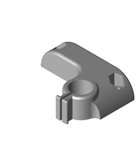
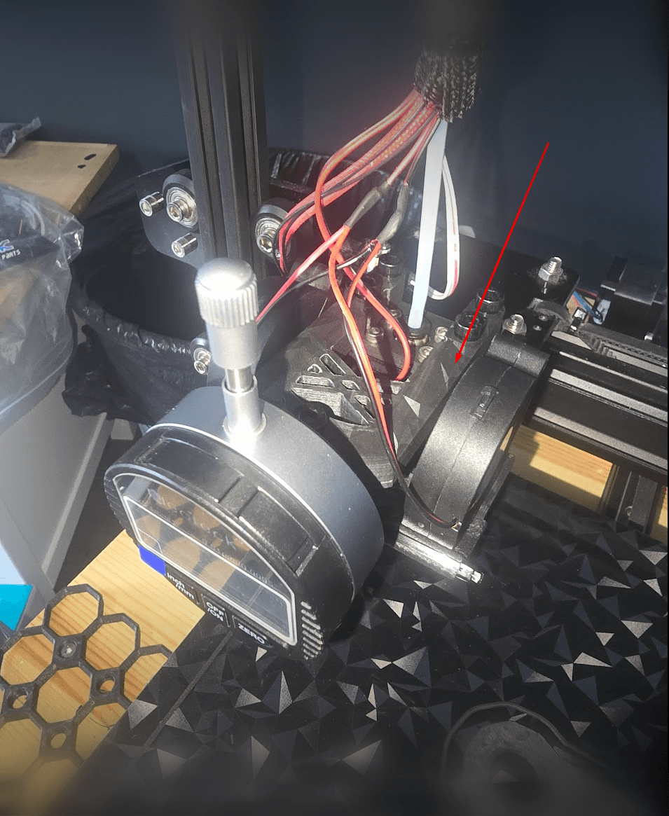
There are a lot of dial indicator mounts out there, but I wanted to make one that would be able to be mounted to a 2020 extrusion, as opposed to your hot end, as there are so many different types out there. I am no longer using the stock CR-10 hot end, and rather than design one for my current one, I wanted something that will work independently.
Note: this is not designed to be used with the hot end/gantry moving. It is all done manually- see instructions below.
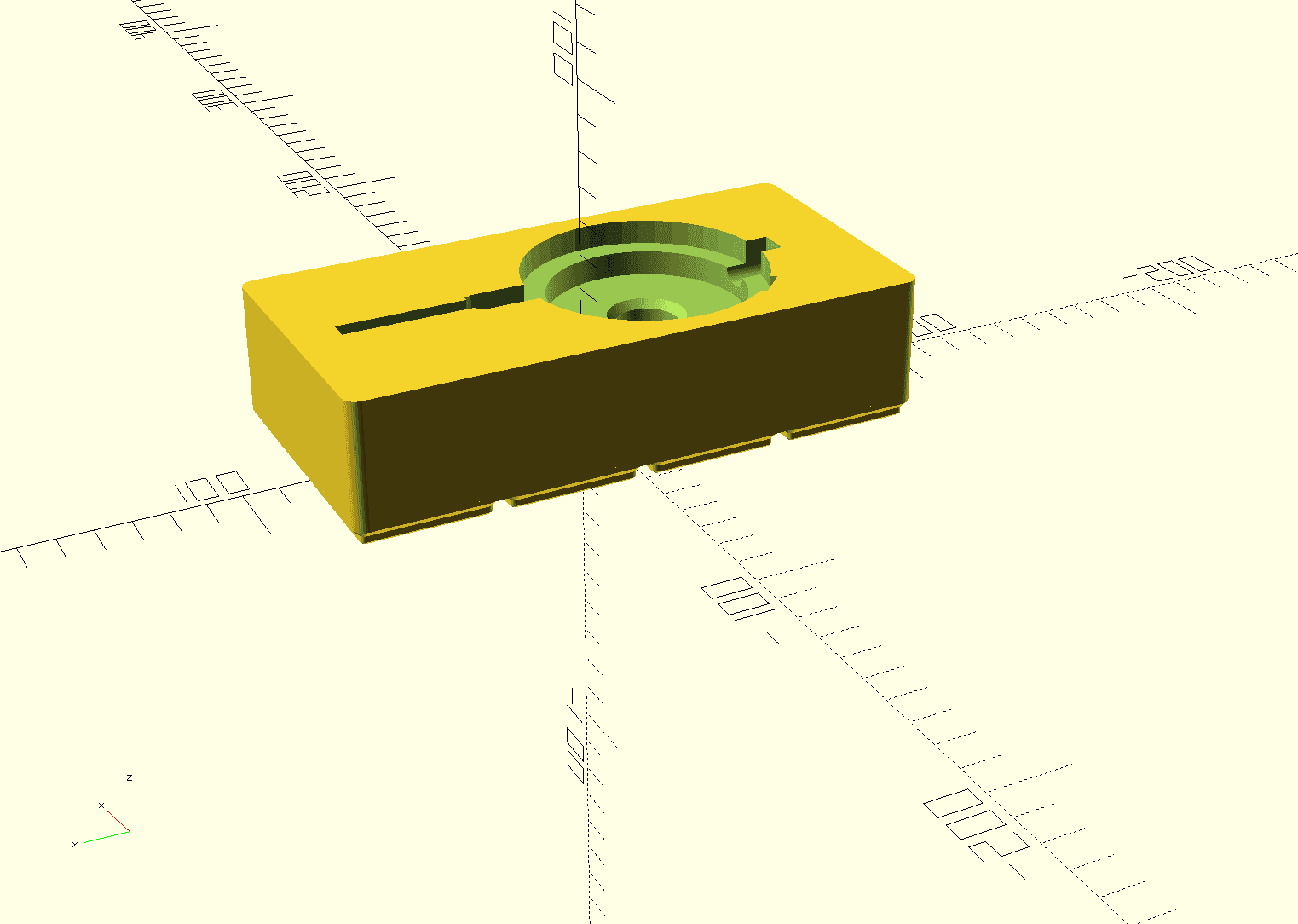
UPDATE 2/17: Thanks to user MikePek for providing feedback that the mount prints out better at 96.5 scaling. I created an updated version that should have the same effect, but does not change the size of the nut hole on the holder. I also have provided the Open SCAD source code if you would like to experiment with another tolerance. Note: you will need to download the original mount this was remixed from to make changes. It is very simple code and you only need to change one line to update the tolerance of the bracket.
UPDATE/NOTE: if you find that mount is a little loose when it is sitting on the 2020, put some electrical tape on the inside back. You don't want it to wiggle around, otherwise you won't get a good consistent reading.
Here is a video showing it in action: https://www.youtube.com/watch?v=bqSuxbQ5n0I
I remixed this one from the CR-10 Dial Indicator mount found here: https://www.thingiverse.com/thing:2412647
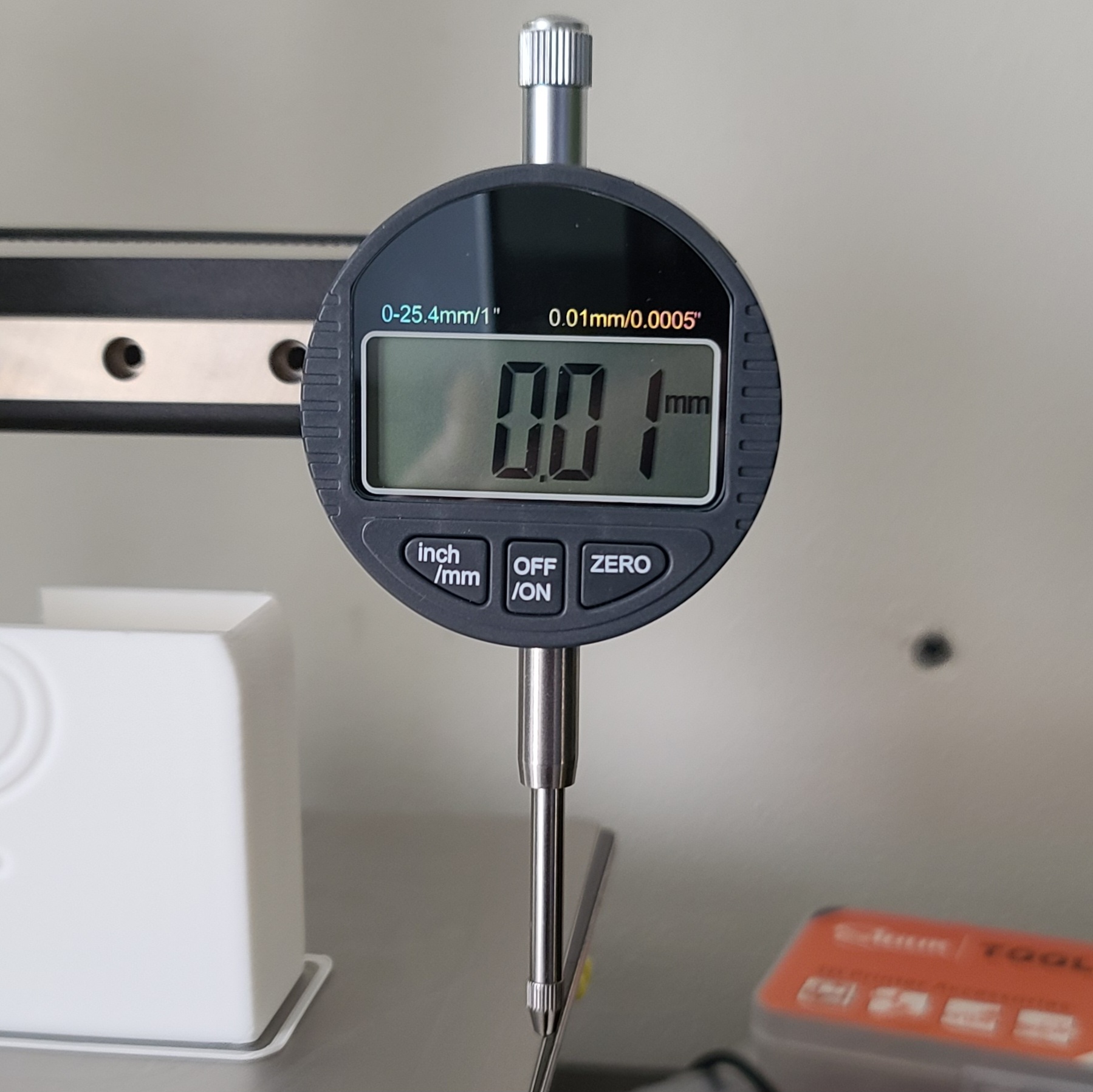
You can get the dial indicator gauge from Amazon, here: http://amzn.to/2ttaAGr
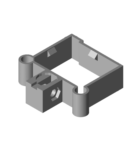
You will also need 20mm screw and nut. Use an m6 screw and nut for best results.
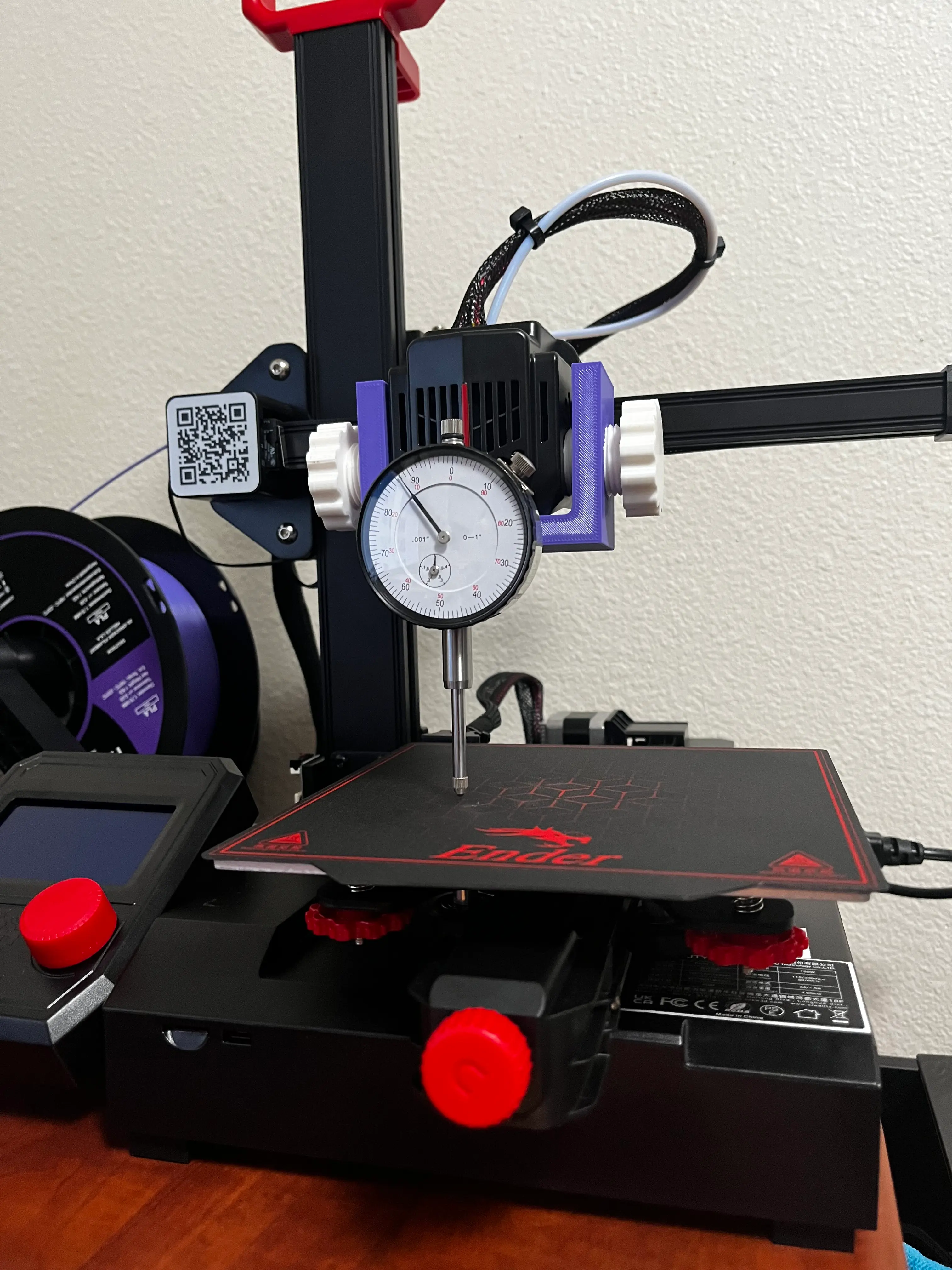
This can be used on any 3d printer that has a 2020 extrusion for the gantry/hot end. There is a small bit of play in the mount (for tolerance), but I've found it to be consistent/accurate.
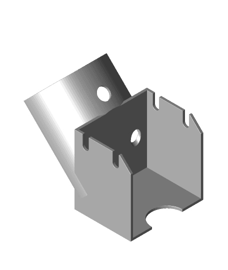
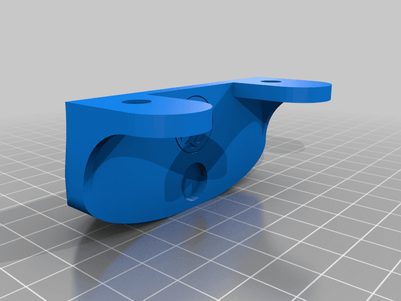
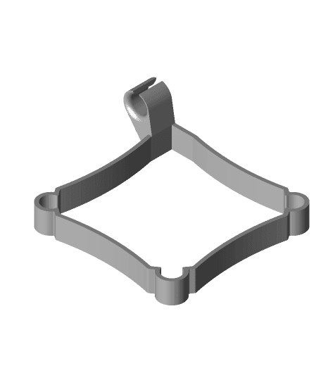
Print it as shown in the image (flat on the bed). I recommend using supports as well. It won't need to print much supports.
Instructions on how I use it (for my CR-10S) - updated for clarity and how I am using it.
First, get everything preheated and into position.
- Preheat your bed to 60C. No need to preheat your nozzle, but scrape off any gunk on the tip.
- Autohome your printer so the extruder goes to the front left corner. Put a piece of paper in between it where there is a slight drag.This will be your reference point, and you don't want to adjust the bed level for this corner after you do this.
- Raise your z axis around 40mm or so using the prepare -> move axis -> z axis menu.
- Disable your stepper motors (under the "Prepare" menu).
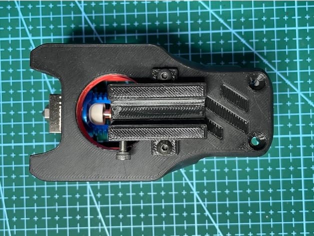
- Move your hot end all the way to the right side so it is mostly out of the way. I am using a Titan Aero mount on my printer, and it slides far enough to the right where I have access to the full bed.
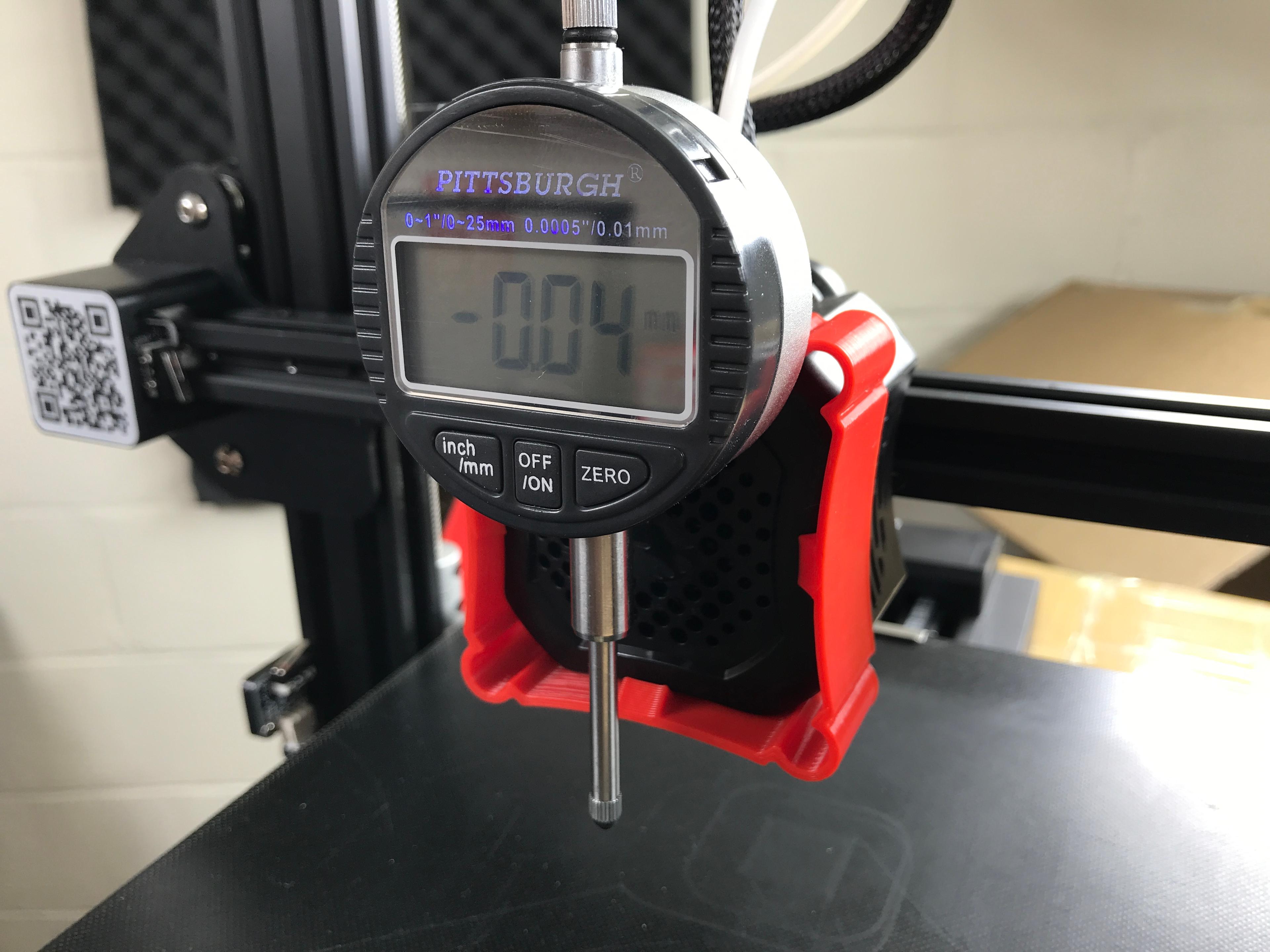
Now you are ready to use the Dial Indicator to check the level.
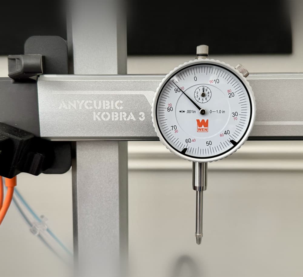
- Snap on the Dial Indicator to the 2020 extrusion on the left side of the bed near the auto home position.
- Manually move the bed forward, to check the back corner. Adjust the bed leveling knob so the number on the dial indicator is about the same.
- Now, slide the dial indicator to the back right and adjust the back right nob. Then manually move the bed backwards and adjust the front right corner.
- Repeat this a few times until you are seeing everything reading the same number. Remember DO NOT adjust the front left corner knob, because that is your reference point.
Once you get the hang of this method, it is only going to take you a few minutes to check level. I've found that my bed stays level for at least 10 prints. After that it's a good idea to run through the check again.
Tips:
- It's a good idea to check to make sure that your x gantry is the same height on both sides before using the dial indicator. You can easily check with a ruler. I find that the left side usually sags by a few mm (it's heavier on the left side, and when you turn off the printer, the steppers do not hold the position as well). If it is not even, use your hand to manually turn the lead screw to get it even.
- If you are using the original glass bed, it's possible it may be warped from the factory, and you'll not be able to get it perfectly level. A lot of people have had success with mirror tile, or going to a hardware store and having glass cut to size.
Ender 3 V2 Dial Indicator Mount
Ender 3 Dial Indicator Mount
universal dial indicator mount
Print Bed Leveling Tool - MGN12 Dial Indicator Mount for 3D Printer Tramming
Magnetic Dial Indicator Mount for Anycubic Mega Hotend Housing
Dial Indicator Mount HF and Ender3Pro v4.stl
Voron 0.1 with MAB Dial Indicator Mount
Maker Select V2.1 fan mount for Dial Indicator
Anycubic Kobra 3 Dial Indicator X-Axis Mount

M6 Nut for Dial Indicator

M6 Bolt for Dial Indicator
Gridfinity Dial Indicator Holder
additional Indicator and Control Mount for Radiator Mount for CNC3020
Digital Dial Mount

Gridfinity 2x2 bin for Mako dial indicator

Gridfinity 1x2 bin for Mitutoyo dial indicator
Mitutoyo Dial Indicator - 2416A Gridfinity Holder

Benyco NKD 125 Blinker Hole Plugs – Universal Indicator Mount Support
Dial Indicator for Ender 3v2