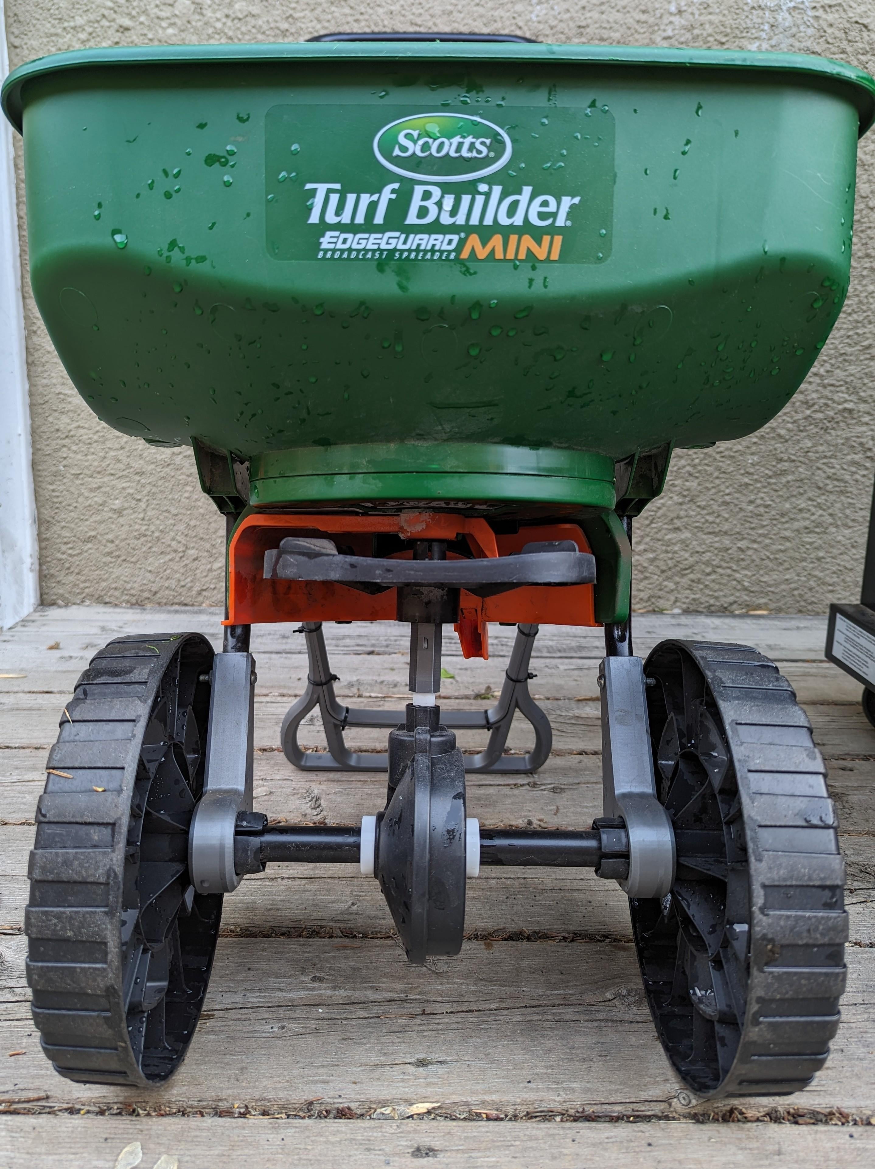


Scotts Edgeguard Mini Spreader Lift Kit
These models solve the issue of the Scotts Edgeguard Mini Spreader causing fertilizer burn lines. It does so by lifting the impeller above the wheels. This should eliminate the issue of fertilizer getting spread into the hollow wheels and deposited into lines. Note that this will increase the spread slightly and experimentation may be involved to get your spreading patterns down.
This fix requires shearing off existing rivets voiding any warranty if one exists. There is also the potential to break the snap-fit plastic of the existing pieces so take care when going through the process. None of the 3D printed pieces have any snap fits as most people would print with PLA and PLA is brittle.
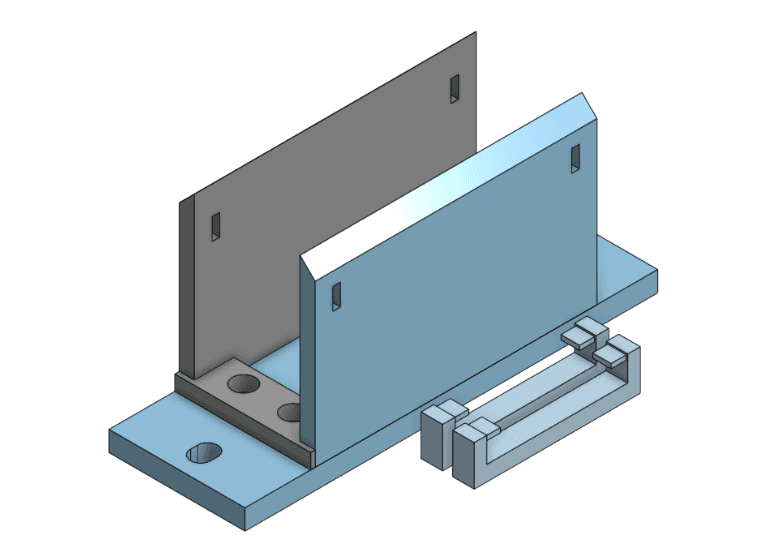
Also note that the radius and arc of the bent wire stand was hard to judge, so 02-stand-extension-outside and 03-stand-extension-inside could likely use some improvement. Perhaps they could also be improved by adding some edges to keep the zip-ties in place.
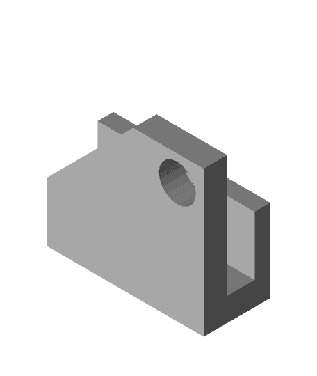
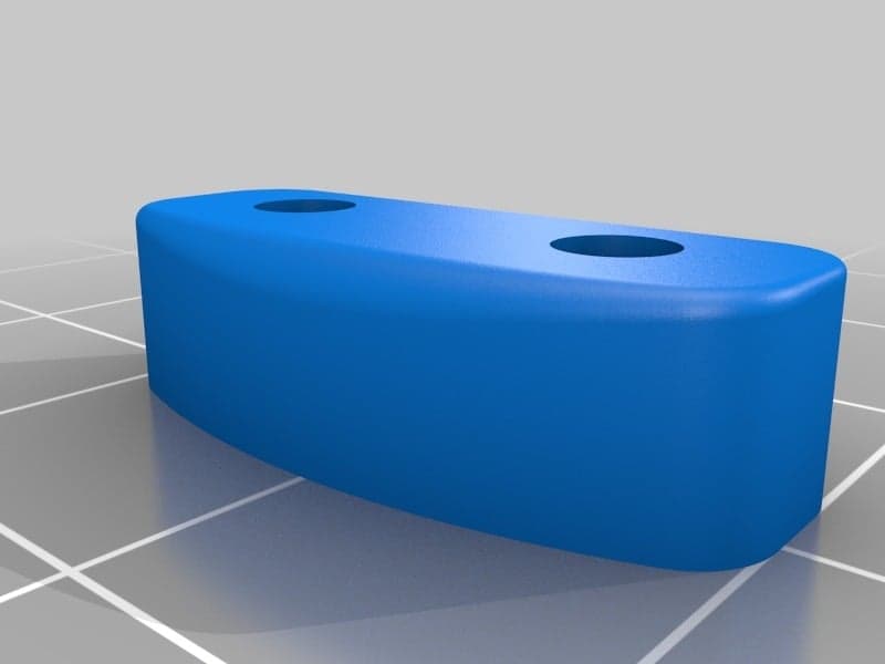
Printed Parts Required: 1x - 01-middle-shaft-extension.stl 1x - 02-stand-extension-outside.stl 1x - 03-stand-extension-inside.stl 2x - 04-wheel-extension.stl
Additional Parts Required: 6x - Zip-Ties 2x - #10-32 x 1-1/4" Machine Screw (or equivalent) 2x - #10-32 Hex Nut (or equivalent)
Steps:
- Remove the left and right wheels by squeezing the snap fit plastic of the wheel "hubs" on the inside of the arms and remove the axle. Be careful to not break the plastic.
- Inside the bucket, note the two pieces of snap fit plastic on the agitator. Expand the snap fits with your fingernails or a flat head screwdriver and pull up to remove it. Be careful to not break the plastic.
- Pull out the impeller and gearbox/shaft and separate them. I believe there are snap-fits on the shaft that would need to be pressed in. Be careful to not break the plastic.
- Shear off the metal rivets on the inside of the existing plastic legs and remove the legs. I was able to do so with a clamping wrench with serrated teeth. I'm sure there exist better ways.
- Replace the existing plastic legs with the 04-wheel-extensions, and replace the rivets with the machine screws and hex nuts.
- From lowest to highest, stack the gearbox/shaft, 01-middle-shaft-extension, impeller, bucket and agitator. With the impeller through the bucket, ensure the snap fits of the agitator are engaged.
- Place the axle back through the gearbox, and reinstall the wheels onto the new plastic legs.
- Place the 02-stand-extension-outside and 03-stand-extension-inside around the rear "bent wire stand" and use zip-ties to clamp them together.
Congrats! You're done. Let me know if there are any tolerance issues or possible improvements that could be made and I'll update the models.
Please note the Create Commons Attribution-NonCommerical-ShareAlike 4.0 International License.

Scotts Edgeguard Mini Spreader Lift Kit

Scissor Lift Kit (1/87 Scale)

Miniature Kei Truck Assembly Kit: Lifted Spec
goBILDA Custom Servo Mount for Cascading Lift kit

Universal lift kit 1/64
Heated Bed Lift Kit for bed insulation - Longer LK1 / Alfawise U20 U30
Babyhawk Race Lift Kit for Runcam Micro Eagle

Babyhawk Race Lift Kit for Runcam Micro Eagle

Chunky Michael Scott - FREE The Office Kit | No Supports, No AMS, No Glue

Dr. Chunkett Brown - Back to the Future Kit | No Supports, No AMS, No Glue

GEN2 115 Tabletop Starter Kit

Chunky Michael Scott Multicolor Nameplates

Lambda Shuttle Vehicle Kit Card - 3D Print Files

Holmes RC-60 Rail Crane Kit 1/87 Scale
.jpg&w=3840&q=75)
artemis lamp bambu light kit

Holmes RC-60 Rail Crane Kit 1/48 Scale

Tamiya High Lift Transmission Lift Set

X-20 DynaSoar

LiftyBox

1/24 1/25 stretch cruiser lowrider bike bicycle
First off, thank you! This is the best one of the few I've seen to fix the mini version. One comment for improvement... the leg stand could use a bit of adjustment toward the upper portion. It needs a little more space in the interior I think to accomodate the original metal wire part it wraps around. I just zip tied it tight and it worked fine. I printed it in PETG.
I think I know exactly what you're referring to. I didn't have the proper tools to figure out the angle and radius of the stand wire so I had to trial and error it until I landed on values that were close enough to work. I just bought a digital t-bevel for something else so this is something I should be able to improve and re-upload.
Thank you! This is amazing!