


Arduino Thermometer Display
Model originally uploaded to Thingiverse at https://www.thingiverse.com/thing:4735897.
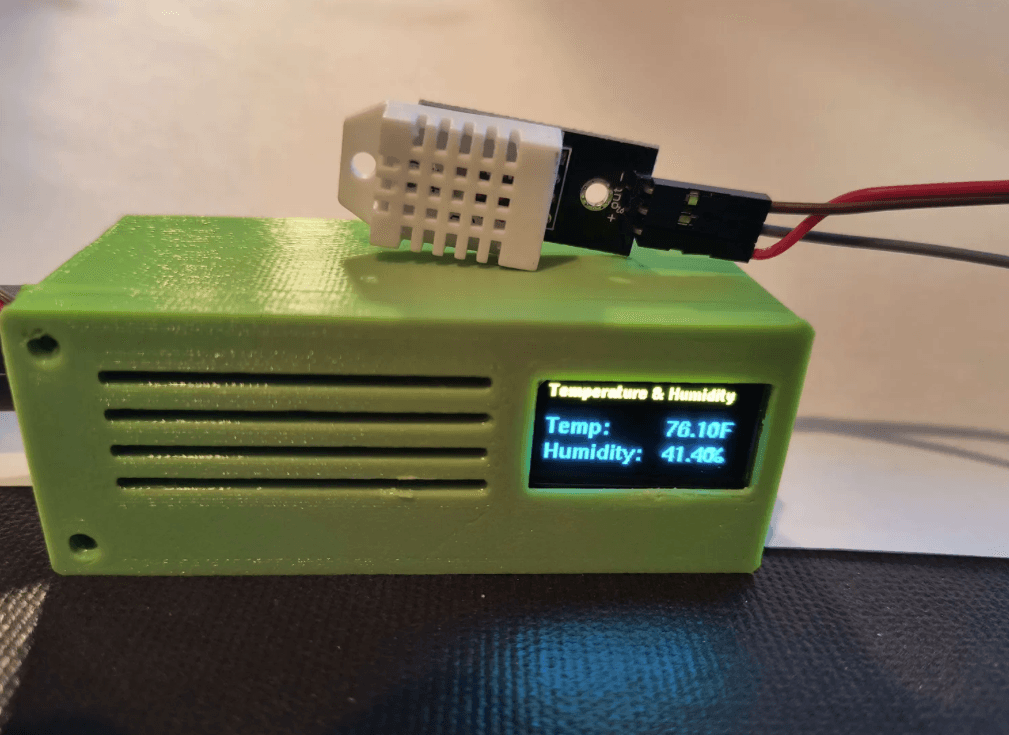
For this project we are building an Arduino-based thermometer and humidity display. It shows the current temperature, temperature index (feel), humidity level and dew point. It also displays a graph of the readings from the past 12 hours.
This design is completely free and shared under a permissive license. Your support is hugely appreciated.
Did you know?Some of our designs cannot be found on Thingiverse. If you are looking for more, check out our premium projects:
https://codeandmake.com/premium
PartsIf you plan to 3D print the case included with this project, you will need the exact components listed below. If you use alternative components they may not fit inside the case.
You will need:
- Arduino Uno R3 (or compatible board)
- Adafruit Proto-Screwshield (Wingshield)
- Velleman VMA412 2.8" Touchscreen Display Module
- DFROBOT DHT22 (SEN0137) Temperature and Humidity Sensor (a DFROBOT DHT11 (DFR0067) sensor can be used instead with a minor code change)
- Panel Mount 2.1mm DC barrel jack - The barrel should be ~11.5mm in diameter and ~16mm in length including the terminals
- A USB mains plug
- A USB to 2.1mm jack cable
- 2x 15-25cm (6-10") ~26 AWG wire - ideally in different colors (e.g. red and black).
For the 3D printed case, you will need the following bolts/screws:
- 2-4x M3x5mm - To mount the Arduino
- 4x M3x12mm - To join the front and rear of the case
- 2x M3x20mm - To mount the DHT22/DHT11 via the 14mm stand-offs
- 2x M3 nuts - For the DHT22/DHT11 stand-off bolts/screws
The DHT22 sensor is said to be accurate to within 0.5C and 5% humidity (the DHT11 is slightly less accurate). However, the electronic components used in this project generate heat, which can affect the sensor's measurements.
In particular, the Arduino's on-board voltage regulator generates a significant amount of heat, so we bypass the voltage regulator in this project by wiring a 5V power supply directly to the 5V pin and we mount the DHT22/DHT11 to the exterior of the case with an air-gap between the sensor and the case.
By doing this we've achieved temperature readings that are within 0.5-1.0C of independent thermometers.
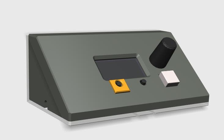
A note on viewing angleThe 2.8" display module has a optimum viewing angle that means it is best viewed from straight-on and below, or straight-on and above, but not both. Therefore, you should consider where it will reside once built.
We've created two versions of the case, meaning you can pick the one that will be best suited to your needs, depending on whether it will mostly be viewed from above or below. You should choose:
- the 'standard' version if it will mostly be viewed from below - e.g. if it will be on a high shelf
- the 'rotated' version if it will mostly be viewed from above - e.g. if it will be on a table or desk - note: a small code change will be required to rotate the display
Before constructing this project, you should upload the code (.ino) to your Arduino.
If you haven't already, install Arduino IDE and configure it ready to program your Arduino.
Please see our tutorial for installing the Arduino IDE in Ubuntu and configuring it for an Arduino Uno. The steps will be similar for other operating systems.
<iframe width="560" height="315" src="https://www.youtube.com/embed/S8TPJp_BgHc" frameborder="0" allow="accelerometer; autoplay; encrypted-media; gyroscope; picture-in-picture" allowfullscreen></iframe> DependenciesThe code for this project has several dependencies on other libraries. We recommend installing the dependencies through the Arduino IDE's Library Manager, which can be accessed via: 'Tools > Manage Libraries...'. Simply search for the following libraries and install them:
- DHT sensor library
- Adafruit Unified Sensor - required by DHT sensor library
- MCUFRIEND_kbv
- Adafruit GFX Library
- Adafruit TFTLCD Library
Please take a note of the following changes which may be necessary, depending on your needs:
DHT11 sensorIf you will be using a DHT11 sensor instead of a DHT22 sensor, you should change the following line:
Before:
#define DHTTYPE DHT22After:
#define DHTTYPE DHT11 Rotated versionIf you will be using the 'rotated' version of the case (for viewing from above), you should change the following line:
Before:
const boolean rotateScreen = false;After:
const boolean rotateScreen = true; Light modeIf you would like to use 'light mode' (white background), you should change the following line:
Before:
const boolean darkMode = true;After:
const boolean darkMode = false; WiringWe recommend wiring up the project and testing it before printing a case for it. This will allow you to test the components and the code (including any changes you make) and it will help you to decide which version of the case to use ('standard' or 'rotated').
As we will be wiring the power directly to the 5V pin, we strongly recommend checking the voltage at the 2.1mm power jack using a multimeter. Only use it if it reads close to 5V!
The jack's center pin is usually positive (+ve), but it depends on the USB to 2.1mm jack cable, so be sure to also check the polarity using a multimeter. Once you've checked the polarity, solder the two lengths of ~26 AWG wire to your 2.1mm jack socket accordingly.
Your Adafruit Proto-Screwshield (Wingshield) may arrive as a kit which will require soldering. If so, we recommend checking out this excellent guide.
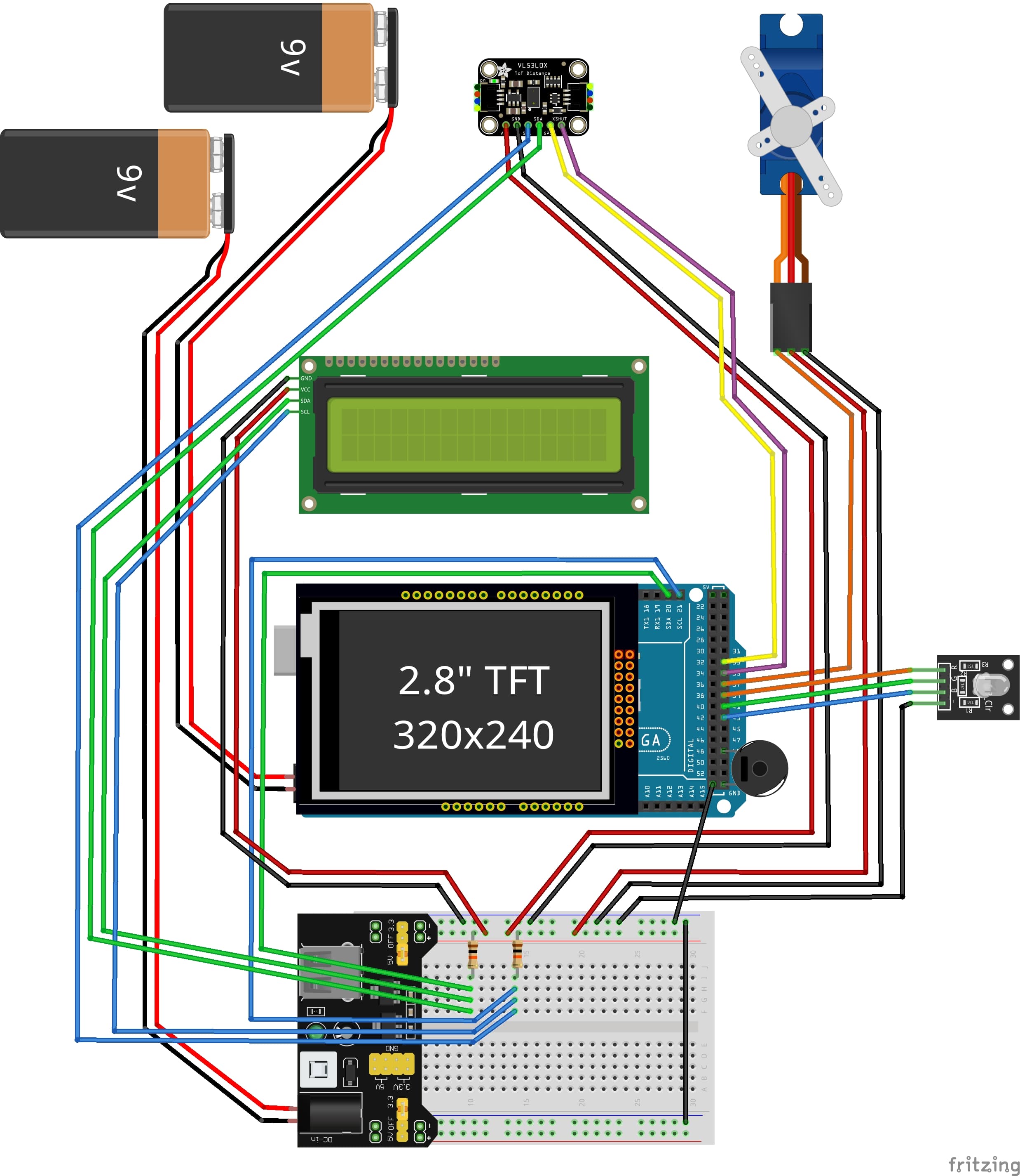
Once everything is soldered, it's time to test it works. Please use this diagram as a reference:
- If you haven't already, upload the code to the Arduino (detailed in the 'Code' section above).
- Insert the Adafruit Proto-Screwshield (Wingshield) into the Arduino Uno.
- Remove the female pin header connector from the cable that came with the DHT22/DHT11 sensor and strip the wires. If you'd prefer not to do this, you will require a cable with a JST-PH connector, but be aware that the colors and/or order of the wires may be different to the original cable!
- Join the DHT22/DHT11's positive (+ve) wire (red) with the positive (+ve) power wire by twisting them together and insert them into the '5V' terminal of the Adafruit Proto-Screwshield (Wingshield).
- Join the DHT22/DHT11's negative (GND) wire (black) with the negative (GND) power wire by twisting them together and insert them into a 'GND' terminal of the Adafruit Proto-Screwshield (Wingshield).
- Insert the DHT22/DHT11's signal wire (green) into the digital pin '12' terminal of the Adafruit Proto-Screwshield (Wingshield).
- Insert the 2.8" Display Module into the Adafruit Proto-Screwshield (Wingshield), being careful not to press directly on the screen, as you could damage it.
- Finally, connect 5V power to the 2.1mm jack and, after a few seconds, you should see some measurements being displayed.
With testing complete, it's time to decide which case to print. Remember, you should choose:
- the 'standard' version if it will mostly be viewed from below - e.g. if it will be on a high shelf
- the 'rotated' version if it will mostly be viewed from above - e.g. if it will be on a table or desk
If you will be printing the 'rotated' version, refer to the 'Code changes' section (above) to make the necessary code change and upload it to the Arduino.
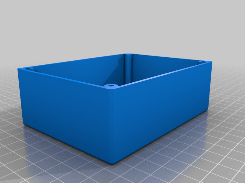
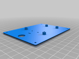
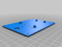
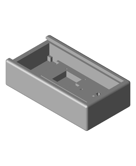
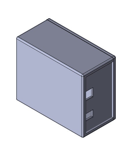
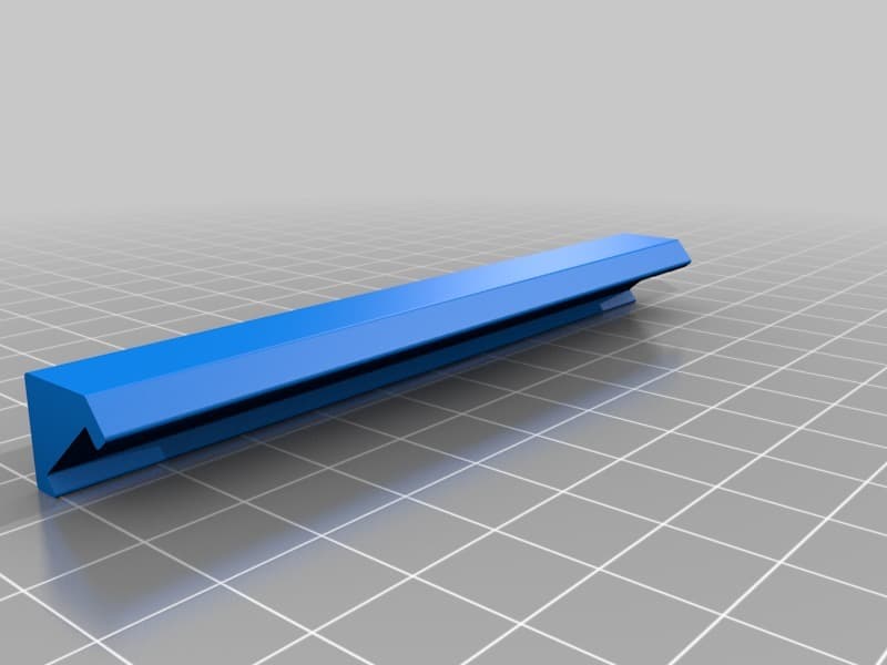
You will need to print 3 parts; a front, a rear and the stand-offs:
Front- codeandmake.com_Arduino_Thermometer_Display_Case_v1.0_-_Front_-_Standard.stl - use this if it will mostly be viewed from below
- codeandmake.com_Arduino_Thermometer_Display_Case_v1.0_-_Front_-_Rotated.stl - use this if it will mostly be viewed from above - Note: a code change is required for the rotated version - refer to the 'Code changes' section (above)
- codeandmake.com_Arduino_Thermometer_Display_Case_v1.0_-_Rear_-_DHT22_-_Standard.stl - use this if it will mostly be viewed from below and you are using a DHT22 sensor
- codeandmake.com_Arduino_Thermometer_Display_Case_v1.0_-_Rear_-_DHT22_-_Rotated.stl - use this if it will mostly be viewed from above and you are using a DHT22 sensor - Note: a code change is required for the 'rotated' version - refer to the 'Code changes' section (above)
- codeandmake.com_Arduino_Thermometer_Display_Case_v1.0_-_Rear_-_DHT11_-_Standard.stl - use this if it will mostly be viewed from below and you are using a DHT11 sensor - Note: a code change is required to use a DHT11 sensor - refer to the 'Code changes' section (above)
- codeandmake.com_Arduino_Thermometer_Display_Case_v1.0_-_Rear_-_DHT11_-_Rotated.stl - use this if it will mostly be viewed from above and you are using a DHT11 sensor - Note: a code change is required to use a DHT11 sensor and a code change is required for the 'rotated' version - refer to the 'Code changes' section (above)
- codeandmake.com_Arduino_Thermometer_Display_Case_v1.0_-_Stand-offs.stl - use this no matter which sensor you are using
If the electronics are still assembled from testing, remove power, separate the boards and remove the wires from the Adafruit Proto-Screwshield (Wingshield) terminals.
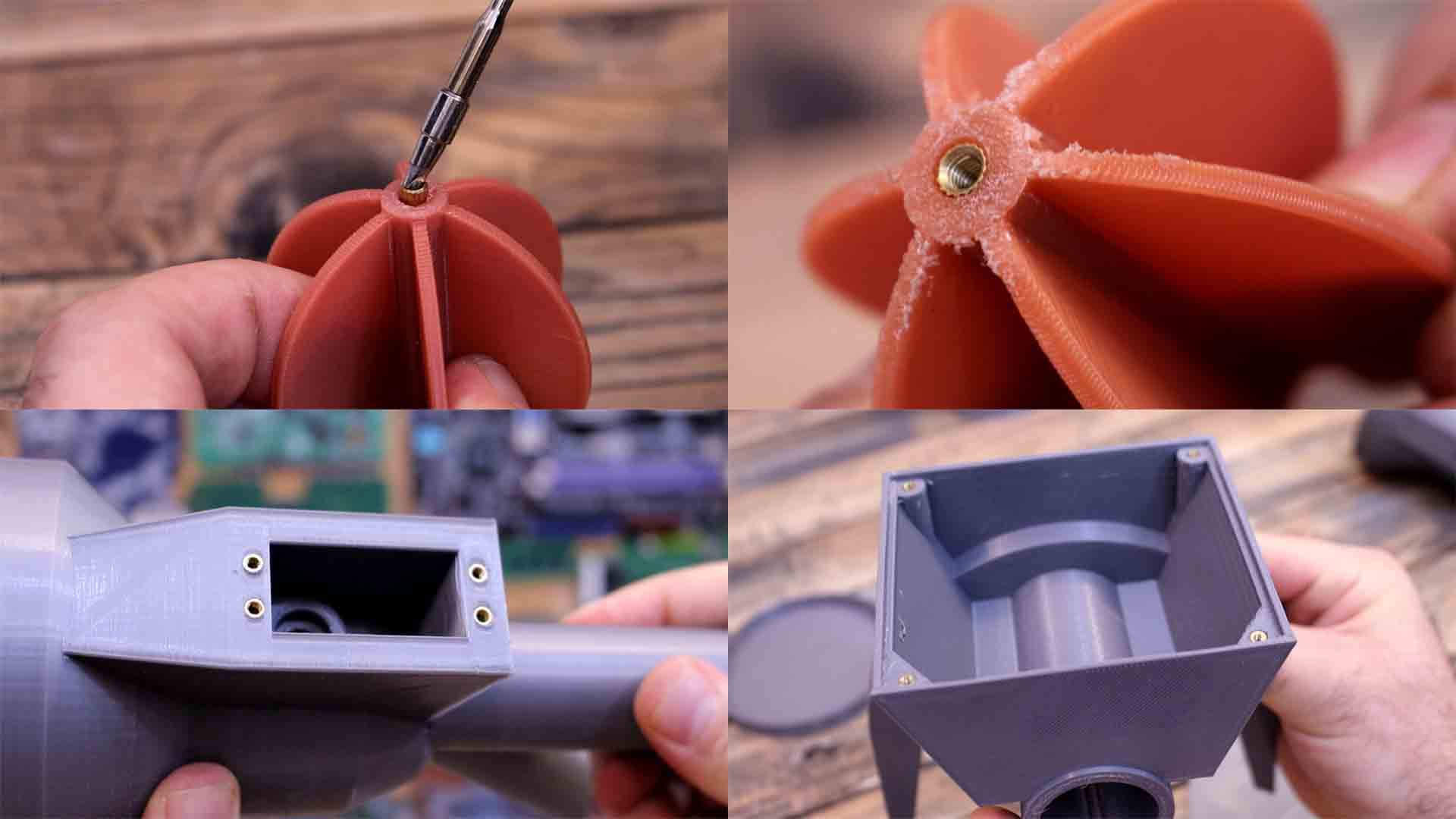
You can now assemble the case in the following order:
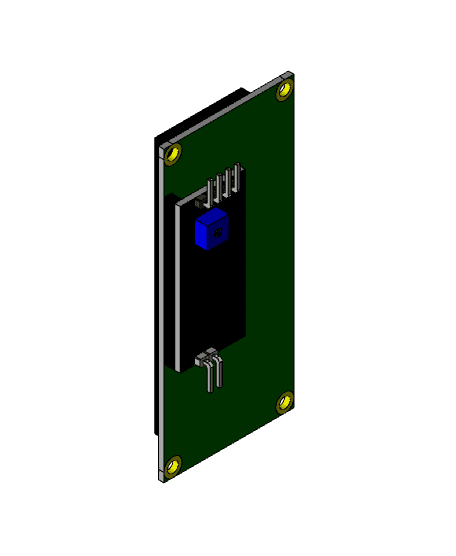
- Insert 2x M3x20mm bolts/screws into the mounting holes of the DHT22/DHT11 PCB
- Thread the stand-offs onto the M3x20mm bolts/screws
- Insert the ends of the M3x20mm bolts/screws into the rear of the case, such that the sensor is positioned on the outside of the case
- Secure the bolts/screws with 2x M3 nuts
- Thread the DHT22/DHT11's cable through the cable slot
- Insert the 2.1mm barrel jack into the rear of the case and secure with the nut
- Mount the Arduino Uno to the rear of the case using 2-4x M3x5mm bolts/screws - we ended up using 3, as we found that the screw head was too large to fit into one of the Arduino Uno's mounting holes
- Insert the Adafruit Proto-Screwshield (Wingshield) into the Arduino Uno.
- Wire the power and sensor wires to the Adafruit Proto-Screwshield (Wingshield) using the 'Wiring' section (above) as a reference
- Connect 5V power to the 2.1mm jack to be sure everything works as expected
- Attach the front to the rear of the case using 4x M3x12mm bolts/screws
- 1.0 (24 Jan 2021) - Initial version
Recommended slicer settings:
- Resolution: 0.1mm - 0.2mm
- Infill: 20%
- Supports: Doesn't Matter
- Rafts: Doesn't Matter
The "Arduino Thermometer Display" models (.stl) are licensed under the CC BY license by Code and Make.
The "Arduino Thermometer Display" code (.ino) is licensed under The MIT License by Code and Make.
We are proud to offer content to you absolutely free.We love to create free content for you. As you might imagine, it takes a lot of time. Supporters help us fund materials and equipment to create future projects and tutorials. To show your appreciation, please use the link below:
https://codeandmake.com/support
We thank you so much for your support!
Arduino Thermometer Display
Arduino Nano + OLED Display Module Box
Arduino GPS with display box
LCD Display
Arduino Nano NeoPixel Ring Base
Aquarium thermometer hook
4x7-Segment Display
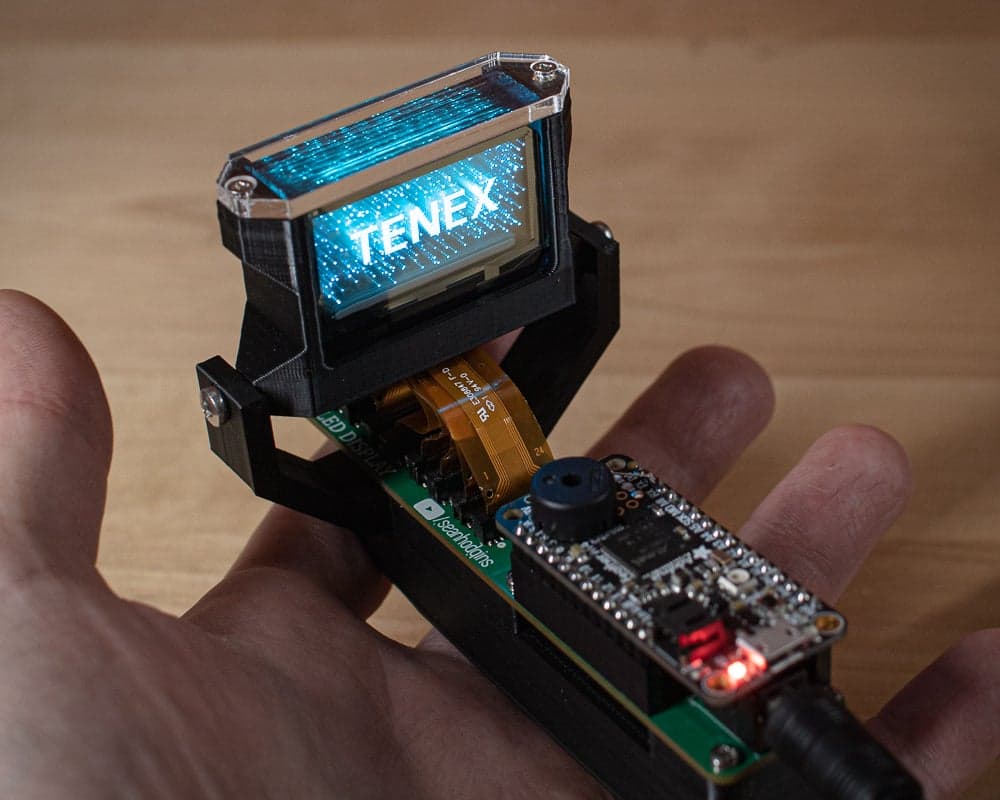
TENEX - Solid State Volumetric Display
Radar Test Bed
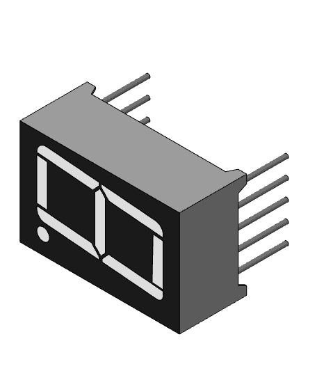
1x7-Segment Display

StandUp Reminder – Take a Break, Move Your Body!

Arduino UNO Mounting Plate
Arduino UNO BOX

16x2 Simple Thermometer

ESPTimeCast – WiFi Clock & Weather Display
Cat Feeder

52mm gauge pod mount for 1.5" display
LeoNerd's OLED Module Enclosure

1.51inch Transparent OLED 128×64 Waveshare Display
Mastermind style safe unlock box