Pivoting Display for Ender 3 - Pro - V2 - Ender 5 - BTT 35TFT & Stock
byBoothy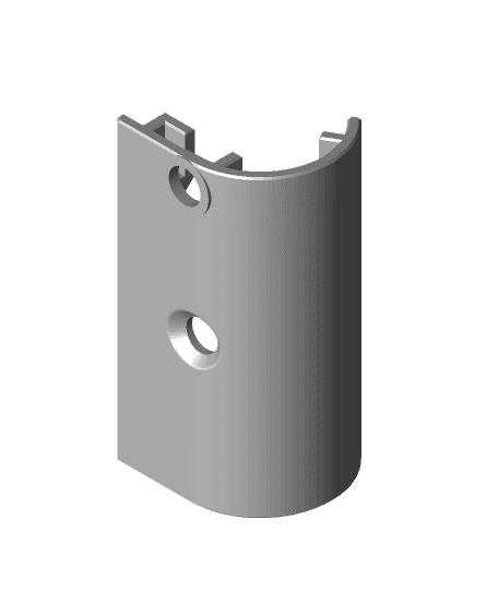
Model originally uploaded to Thingiverse at https://www.thingiverse.com/thing:4624670.
There is a newer version of this thing here: https://www.thingiverse.com/thing:4635067
Update:18\10\20 I had noticed some differences with the alignment of the touch panel on the BTT display with my various units. I have therefore offset the fascia panels of my original design by 1.9 mm to be in alignment with the BTT schematic of the display which I am hoping is correct. All parts ending in V1.1.
This is a Display housing for the BTT 35 TFT E3 & Stock Ender 3 & 5 Displays which includes a pivot function to aid viewing angles. Ideal for work areas with awkward lighting or when the printer is installed at a higher elevation like a shelf.
In addition to pivoting this housing also includes:
1.Storage for an additional Standard & Micro SD Card.
2.Access to the onboard display USB socket.
3.Onboard Display Reset Button.
4.I have also included a basic side panel that just as a slot to the onboard SD reader if you do not wish to use a SD Card Adapter.
5.Display Housing Design for the Ender 3 & 5 stock Display
6.Display Housing Design for the Ender 5
7.Ribbon Clip to tidy the Ribbon Cable and prevent snagging.
Installation Notes
1.The Ender 5 version will require an longer ribbon\serial cable compared to stock. 400 mm is spot on..
2.I always suggest using a SD card adapter to protect the onboard SD card reader from wear & tear. knacker the onboard reader and its a new board! For the BTT TFT35 I use this: https://www.amazon.co.uk/gp/product/B01C8EDHE6/ref=ppx_yo_dt_b_search_asin_title?ie=UTF8&psc=1
3.I will try and upload a more in depth Installation guide when time allows.
4.The holes for the T slots are M5 but M4 will also work if more readily available.
5.You will need 7 x M3 thermal inserts: https://www.amazon.co.uk/gp/product/B01GO4O0OW/ref=ppx_yo_dt_b_search_asin_title?ie=UTF8&psc=1
6.If using the card adapter insert into the board before assembling the housing. Likewise insert the reset button before assembling the housing.
7.Use grease rather than oil to lubricate the 3D printed threads. You may need to use the Pivot Knob as a Tap the first time used to free\clear the thread.
8.On an Ender 3 V2 you may need a longer ribbon cable or cable extension to achieve the full 90 degrees pivot.
9.Make sure all the bridging on the inside of the Reset Button is clear or it may bottom and not function correctly.
10.I have included some slots in the back of the base under the cable apertures for cable ties to help wire management. It is worth inserting the ties first before fixing the base panel to the assembly.
11.You will need various M3 Hex Bolts including 6 mm, 8 mm and 10 mm.
12.With the Pivot Knob tightening from plastic to plastic faces the knob grips quite easily so the knob does not need to be over tightened to arrest the pivot.
13.There does appear to be some movement between the display circuit board & the actual touch screen panel. I have noticed that due to this one of my display menus are slightly offset. I am not sure what to suggest here other than tweaking the position of the touch panel if the screen appears to be offset.
Printing
1.All Casing elements printed @ 0.2 layer height, 25% infill and 2 perimeters. Smaller pieces and both knobs 100% infill.
2.Print the Base Panel & Extrusion Mount with at least 3 perimeters and 30% Infill. Personally I used 4 perimeters and 30% infill to maximise rigidity and reduce any potential flexing.
3.As per previous designs there are some sacrificial layers to holes to help bridging, they will need clearing prior to assembly.
4.The Upper panel as a integrated support foot to help stability which will need removing with side cutters.
5.To take advantage of the BTT LED illumination for the Control Knob you can dual colour print the knob with Clear PLA at the base. You may need to enlarge the Lower Panel hole a little to maximise the LED illumination.
Printed with AMZ3D Black PLA Amazon Basics Blue PLA Eryone Orange PLA Amazon Basics Red PETG
Printed on my HEVO, Ender V2, Ender 5 & CR10S.
The matching SD Card Adapter can be found here: