Ender 5 Core XY with Linear Rails MK2
Model originally uploaded to Thingiverse at https://www.thingiverse.com/thing:4777606.
Update:30\08\21 Uploaded CAD Files in Fusion 360 & Step Formats.
Update 22\05\21
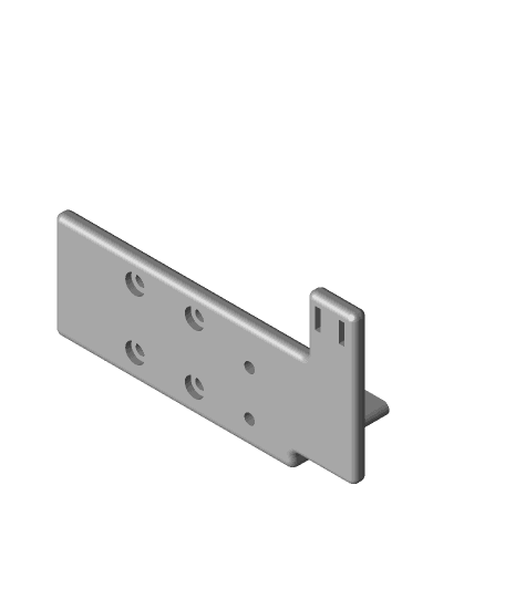
Uploaded Step files for Linear Rail Mounting Plates.
Update 06\04\21
Uploaded a revised Mounting Plate for the V1.5 Orbiter Extruder with a reinforced\ more robust WM Upstand.
Update 31\03\21
Based On feedback by TheOML I have uploaded a revised BL Touch Bracket which is 5mm longer. This part is untested. It will require a small amount of support to print effectively. WIP.
Update 31\03\21 Uploaded a revised Mounting Plate and Adapter Plate for the V1.5 Orbiter Extruder. The Extruder hole Mounts slightly conflict with the existing Duct Base mounts so I have had to design an additional adapter plate to overcome this short term. Long term I will design a specific mount for this but this will mean printing a new Duct Base to suit. I have tested this arrangement on another prototype printer but not specifically the MK2 conversion so please treat this as WIP.
Update 25\03\21 I have revised the Duct Base with a side access slot to allow the easier removal and insertion of a Bowden tube clip & collar. I have installed and tested this and insertion and removal are relatively easy with a small terminal screwdriver or similar tool. I had to slightly move the WM clamp fixing centre so I have also updated that part has well. Revised duct base step file also included. Revised the rear fan cable tray to insert the RH fan cable more easily. Minor design tweaks to improve print quality
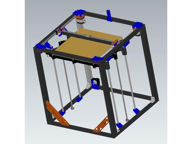
This is my second Core XY conversion kit for the Ender 5 with Linear rails.
Test Print Video here: https://www.youtube.com/watch?v=H8vL2GeMYMQ
Previous version here: https://www.thingiverse.com/thing:4650517
As per the previous version a big shout out to Scott3D for his fabulous work on the Hypercube Evo which I have taken the belt tensioner detail from and a massive thanks to barnabyQ for his Ender 5 Pro 3D model over on Grabcad. This made things so much easier.
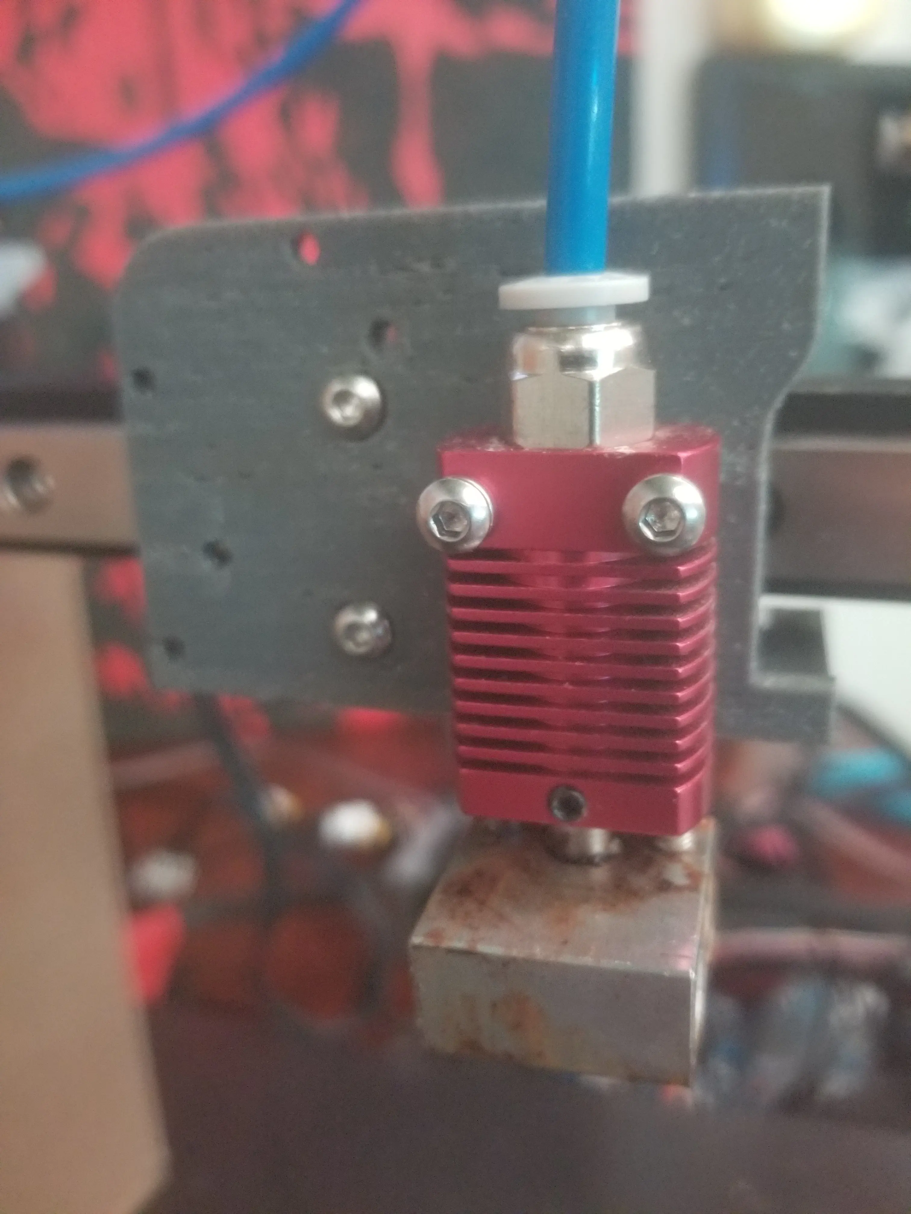
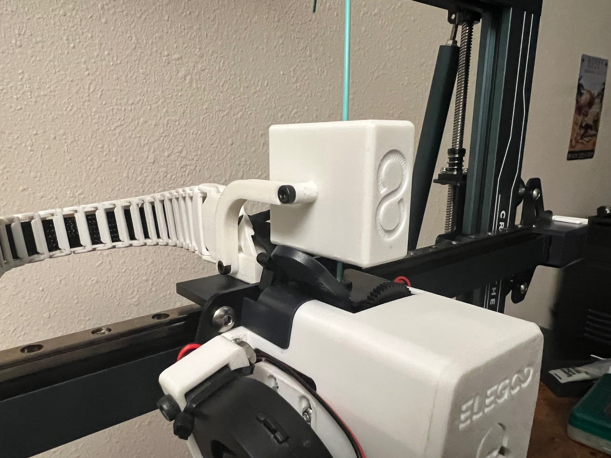
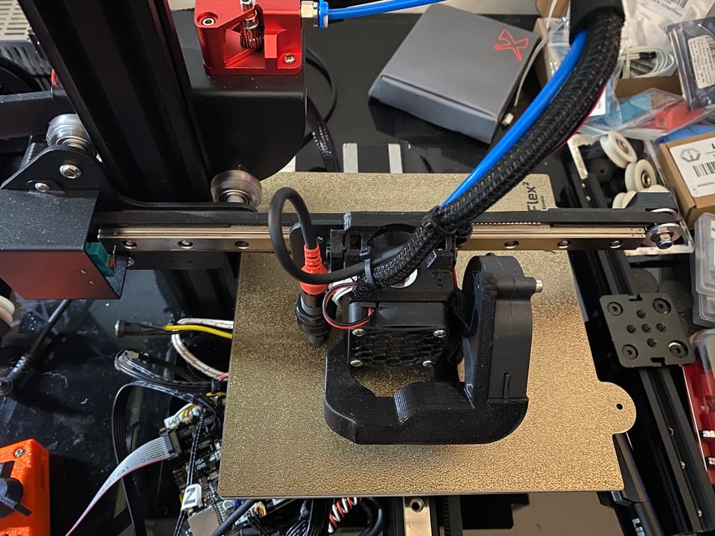
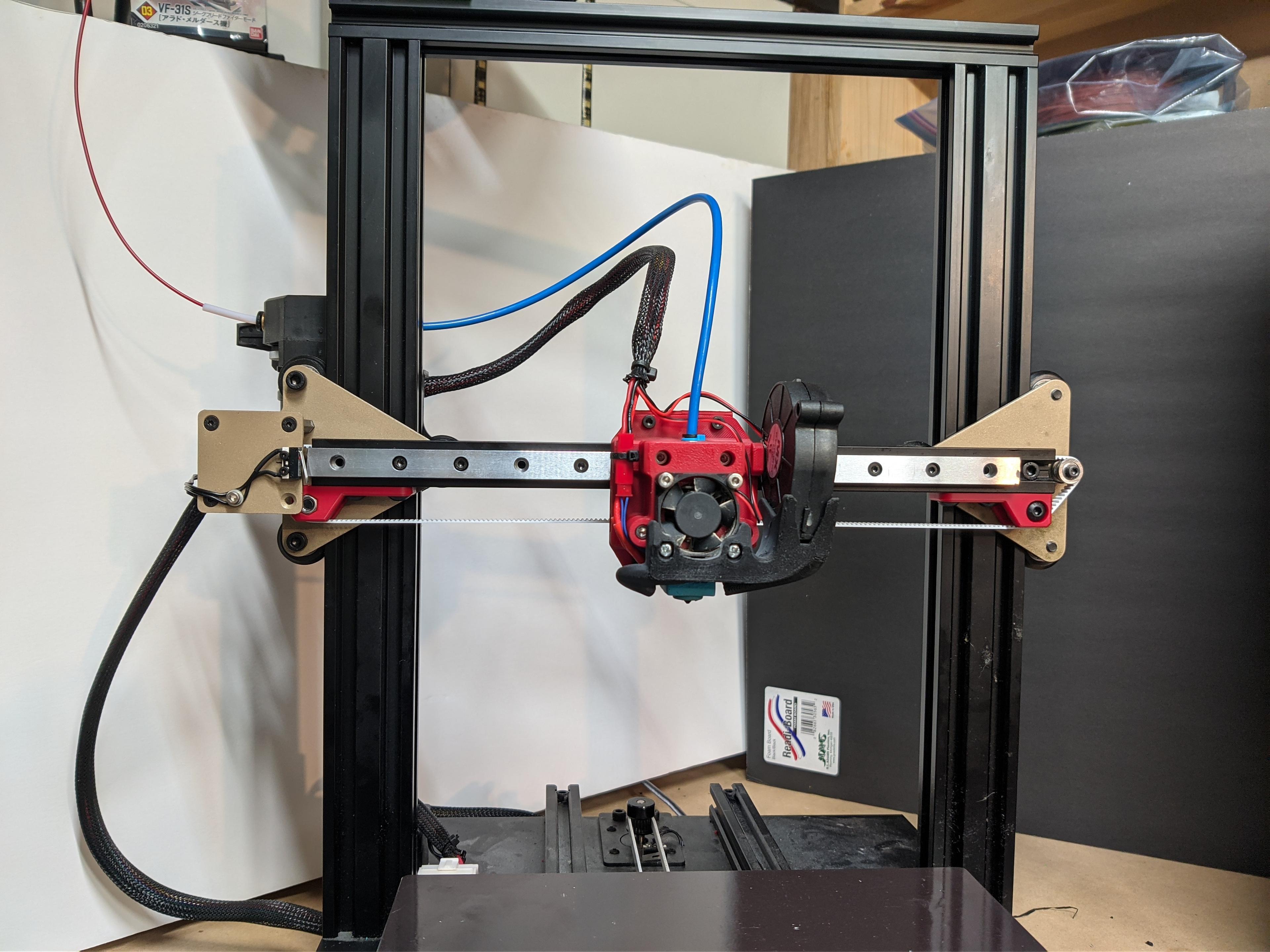
The major difference with this version is that I have placed the hot end assembly closer to the linear rails so there is much smaller cantilever from the nozzle to the linear rail. This should result in reduced inertia. The hot end assembly in this version is also very bespoke reducing the size. The belts are also immediately below the linear rails which should also help speed of printing.
Other Improvements:
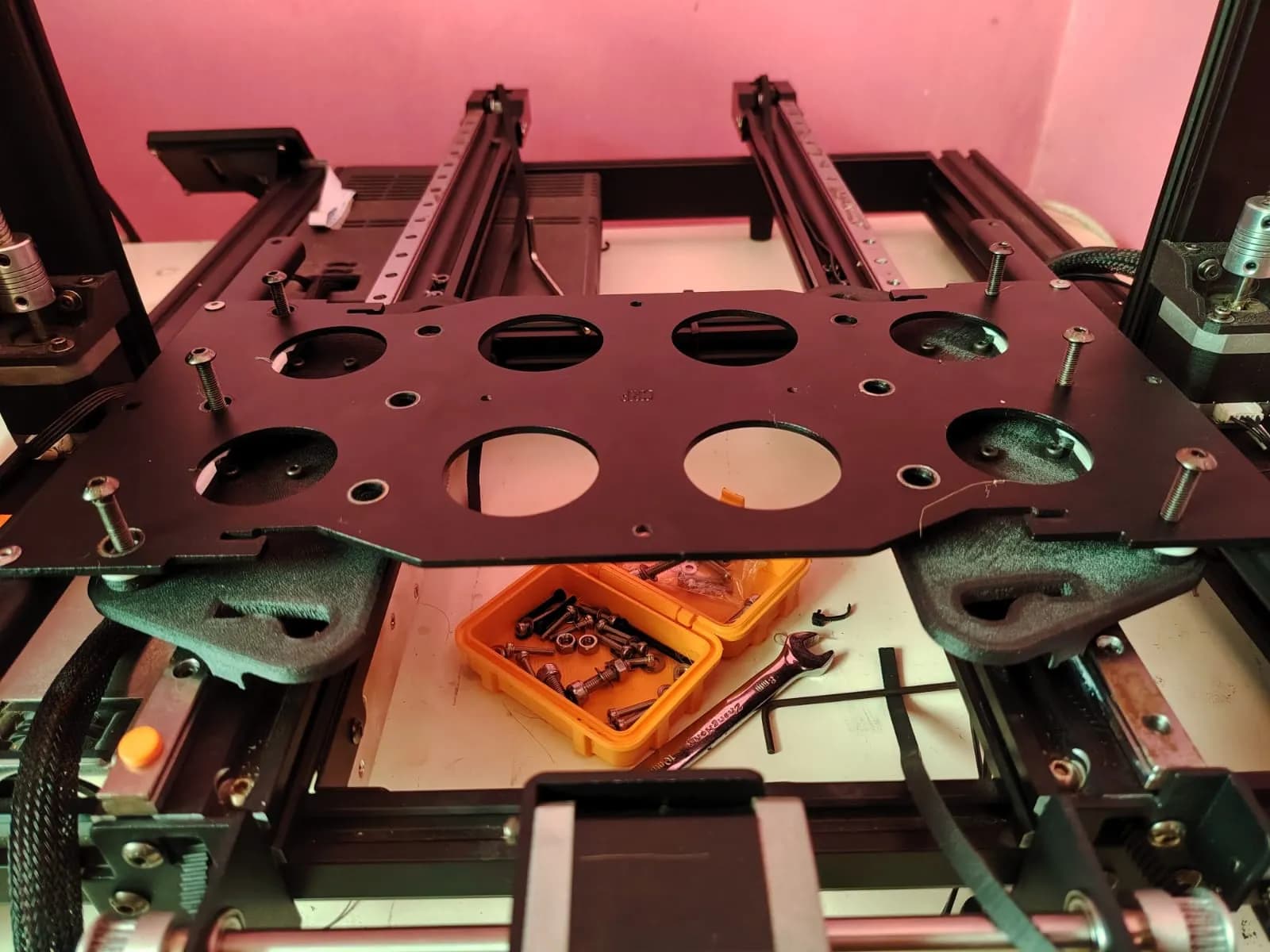
The Linear rails mounts although additional parts allow for much direct easy mounting than mounting directly to the extrusions.
Includes an optional Extrusion motor mount to it to be sited in the middle of the side frame. In addition to making it much easier to change filament as opposed to the rear of the frame, being centrally mounted allows the bowden tube to be slightly reduced which is always a good thing.
Includes a set of vertical wire management ducts to tidy up the messy stock cabling. Designed in two parts to allow printing on the Ender 5 build plate. There is also a second upper duct which can be used with the stock metal motor mounting plate if preferred
Optional Direct Drive Stock Extruder plate.
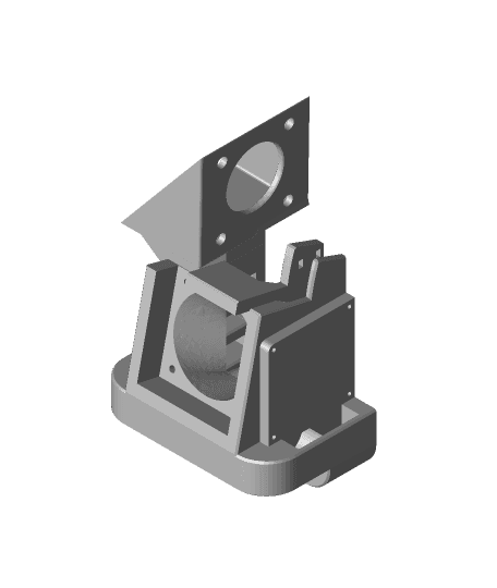
I have designed an offset fan shroud for a V6 compatible heat sink which allows a BL Touch to be mounted at the front but still mostly clear of the front facing 3010 heat sink fan. There are also alternative cover plates for without any sensor and one with an offset down stand potentially for a LED light source and wiring.
The firmware changes were relatively simple, there are only a few comments to tweak. I did however have to invert the direction of the X & Y motors. Uncommenting Z_CLEARANCE_BETWEEN_PROBES & Z_HOMING_HEIGHT stopped the Z axis from trying to drop to clear when homing. I have included my config file within the upload for reference.
The conversion will easily allow for the stock 220 x220 build volume and allows for the full 235 x235 dependent on duct design. I have not yet designed a 5015 fan duct set.
I have since attached a Optical End Stop to the X axis to tidy up all the cables. I had to extend a 1 metre cable to do this and provide a separate power feed to a spare 5v pin on my BTT E3 Mini board.
I have also remixed a fixed variant of my Slim Display Housing to sit inboard of the Ender 5 Frame here: https://www.thingiverse.com/thing:4650597
I have uploaded step files for the Duct Base, Bowden Tool Plate and XY joiners for customisation.
Installation
1.I have classed this has WIP because I have not yet been able to provide a detailed installation guide. I have however included a high res annotated screen grabs for the assembly and a sample BOM for the parts in the upload to get you started. Please comment or message me for further technical information.
2.The Bill of Materials is only indicative and the relevant parts could be purchased much more cost effectively at the likes of Aliexpress. I had most of the parts in stock so personally this conversation cost very little.
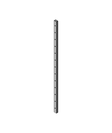
3.The forward idlers are created by removing the front to M5 2020 frame fixings and replace them with a 80mm threaded bar. This is a very simple but strong foundation for the front idlers. I have not seen any side effect in rigidity terms but you may want to attach some additional corner brackets if concerned about the rigidity of the frame overall.
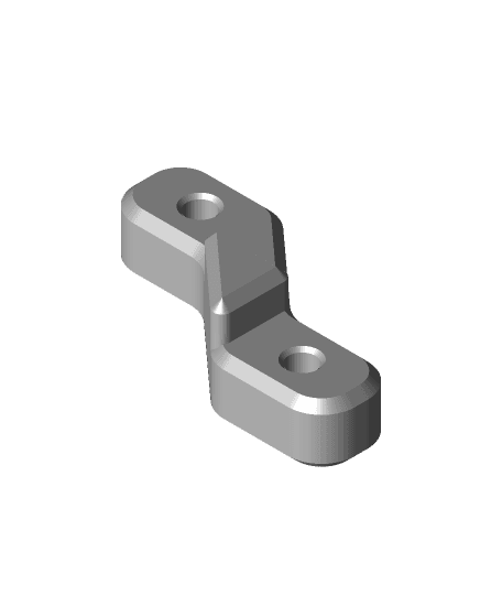
4.With XY joiners there is no perfect print orientation due to the stress by the belts on both axis. I have therefore included 4 x 40 mm long M3 tie bolts which fasten across the print grain to help reduce any potential delamination of the layers. I have found out of experience any many prototypes with my HEVO that this little mechanical indulgence is well worth it in terms of longevity.
Printing
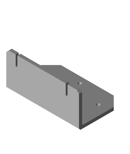
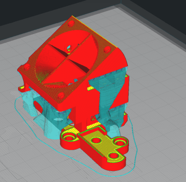
1.All parts print without supports except for the Bowden Tool Plate, which may require some custom supports under the wire management port if it is printed vertically as uploaded. The tool plate will print fine horizontally just not quite the same surface finish. There are some sacrificial layers across some holes to help bridging which will require cleaning through.
2.Due to the belt tension applied these parts need to be printed quite strongly. Therefore I have printed all parts with at least 30% infill and 3 layers. I would suggest all parts near to the hot end and bed should be printed in PETG whilst others will be fine in PLA if sufficient layers and perimeters are adopted. The black parts are ABS, the ABS parts were printed with no cooling and a 10 layer brim to reduce warping.
3.Printed with Amazon Basics Yellow PETG @2.5 layer height, 40 mms on various printers. Black parts Verbatim Black ABS, 2 layer brim, no part Cooling (except bridging), 50% infill, 3 perimeters.
Quick Tips
1.The Belt Tensioner assembly is much easier to put together with the printer on its front and therefore facing the parts laid flat. Leave a reasonable amount of spare belt for tensioning before trimming the belt.
2.Use a M3 tap to clear all the plastic from the thread inserts prior to assembly, it makes life much easier.
3.The thermal inserts I have used have an average OD of 5.2 mm. Therefore I use a 4.7mm insertion hole. Smaller inserts may require a smaller hole size. They are listed in the BOM.
Ender 5 Core XY with Linear Rails MK2
Ender 5 Core XY with Linear Rails
X-Axis Linear Rail For MGN12 Linear Rail
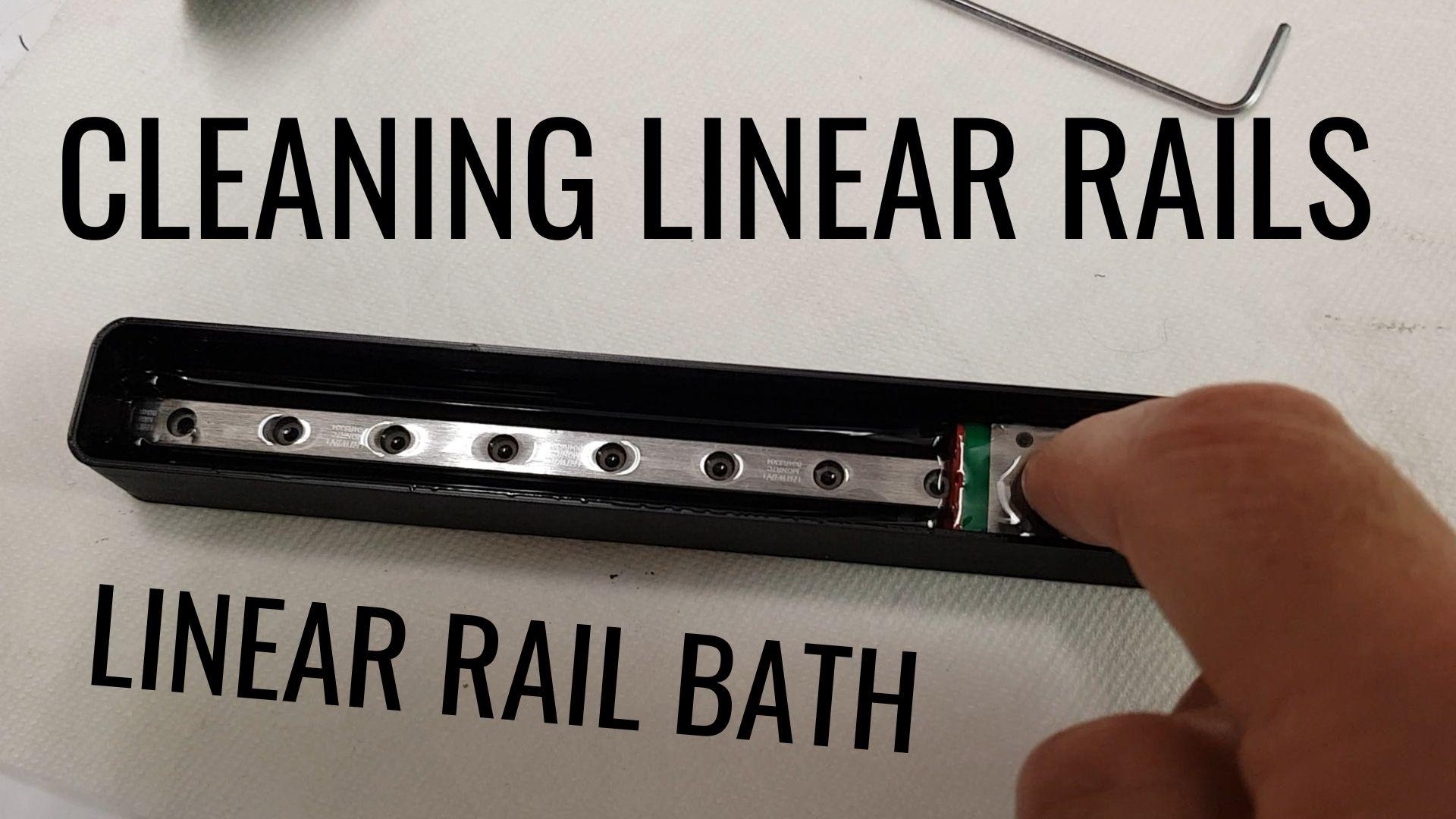
Linear Rail Bath - Clean your linear rails
Anycubic Mega Zero Z-Axis Linear Rail
AnyCubic Mega Zero V1 Y-Axis MGN12 Linear Rails
MGN12 2040 Carriage Stop-Linear Rail Alignment Tool.stl
Anycubic Mega Zero X-Axis Linear Rail
.jpg&w=3840&q=75)
MS DD Linear rail mount for Creality / Ender printers
Ender 3 X-Axis MGN9 Linear Rail Carriage
Kobra Max Linear rail y axis upgrade
Neptune TBStron3D Linear Rail Chain Adapter and Run Out Sensor Relocation
Ender 3 Linear Rail Mount for BIQU H2
Kingroon KP3 X Axis Linear Rail Mod
MGN12-H Linear Rail 400mm Long-3D Distributed.step
Satsana - Linear Rail / Direct Drive Stock for Ender 3v2 Remix

Thinker S dual blower hotend - Remix for Linear Rail
Simax 3D X Axis Linear Rail Conversion
Ender 3 Hero Me 5 no Y offset for linear rail and direct drive BMG
X5SA to VzBoT Minimal Linear Rail Conversion "Pooron V1"