


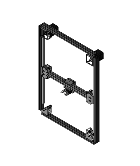
SolidCore CoreXY 200x300 with Stealth XY Mounts
All Metal CoreXY Platform The SolidCore CoreXY is designed to be a highspeed workhorse for repeated use. All-metal-parts and components will give us the durability and repeatability needed. But we want people to have the option to use 3d printed parts so they can upgrade later on. Solid all metal parts are durable and less likely to deflect at high printing speeds.
- Modular & Scalable
- All Metal Parts
- Linear Rails
- Crossing Belt Path & Layout
- Enclosure
- Triple Z-Axis For 3-Point Bed Leveling
- Open Source
- Kinematic Bed Mounting System
Aluminum Parts The aluminum components are also less likely to breakdown over time when introduced to the forces and heat from repeated use.
Simple & Compact CoreXY Design While the SolidCore design is still a work in progress it’s slowly but surely materializing. For now we decided to go with a simple but functional design but still have many plans that will later be adapted for additional tools and configurations.
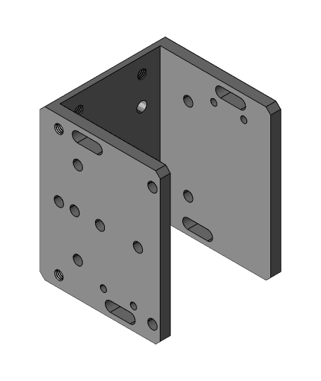
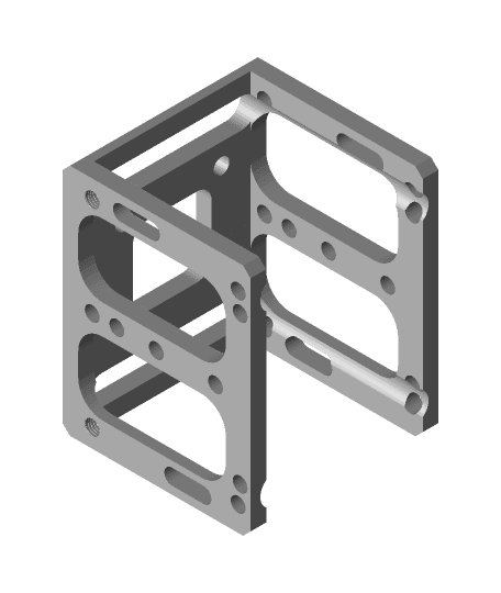
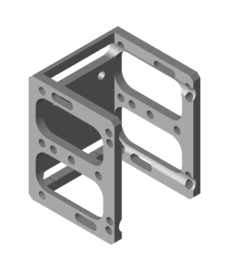
Mechanical Arrangement With the motor and idler mounts placed on the inside corners of the frame gives us clearance to easily mount an enclosure. This configuration also eliminates any design constraints of overall length and width which maker the machine completely modular and scalable.
CoreXY Mechanism Belt Path The corexy motion system uses crossed belts instead of offsetting the stepper motors giving the belt path a clean run. Simply offsetting the motors may give a much better alignment path. Belt Routing & Layout The belts don’t have to cross if the pulleys are at different z-levels, I always thought that was bv the difference between the hbot corexy was the corexy belts crossed at the m segment. But the difference between hbot and corexy is that hbot has a single belt on a single plane, corexy can have either 2 “non-intersecting planes” or a single plane + idlers on different levels to keep the belts from touching. Belt System Hypercube for example doesn’t have that “x” because the belts are on different planes. The Railcore has the crossing belts but the belts are on different planes. Crossing Belts
- Motors at differing planes = straight belt paths
- Motors at same plane = Crossing belts
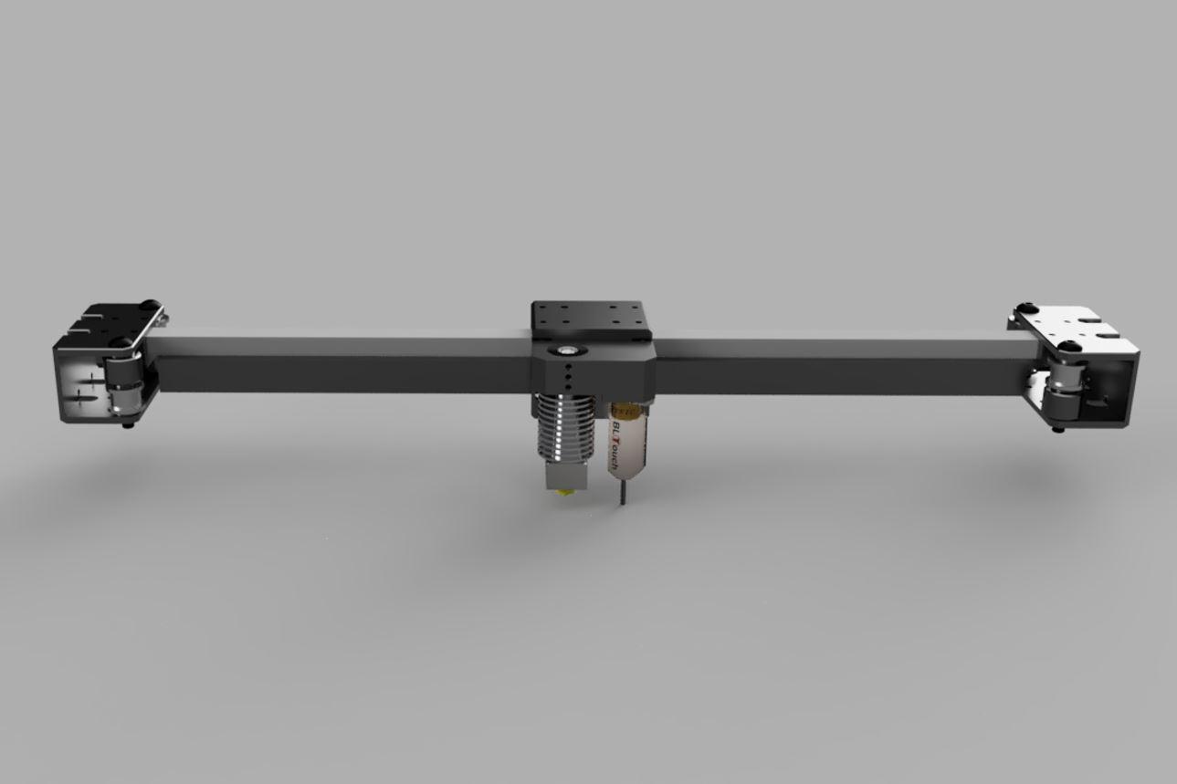
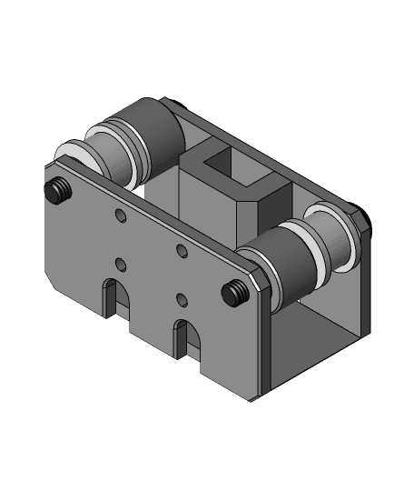
Gantry & Carriage Design The carriage and gantry are designed to be light weight and strong. We currently use c-shaped aluminum stock because it reduces machining time. The reduced machining time and minimized waste helps but it’s a compromise. That's going to change soon.
X-Carriage We’re aiming to balance the pull to the center of carriage instead above it or below. It seems to be more rigid and minimize deflection. The belts are somewhat within the same plane of the three linear rails to avoid rocking cantilever loads that other designs may have with the belts up high or down low.
Belt Tensioning Belt tensioning is done with the XY motor mounts. The XY mounts have slots to allow the belt tension to be applied by pulling the motors back.
Linear Rails We’ll probably make some changes such as reorienting the the y-axis linear rail into a vertical position similar to the RailCore but the current horizontal version will be easier to adapt an E3D Toolchanger.
Enclosure With the motor and idler mounts placed on the inside corners of the frame gives us clearance to easily mount an enclosure.
Build Area Configuration Eventually we would like to have a spreadsheet or configuration tool that will allow you to input the current frame or linear rails that someone already owns and output length and rail options. Or if you’re aiming for a specific build area, you can input the data and it will output the frame and rail length options.
Z-Axis Design
- Triple Z / 3-Point Bed Leveling
- Kinematic Bed Mounting
3-Point Bed Leveling Three point bed leveling uses three independently driven lead screws to automatically level the bed and compensate for flatness.
SolidCore CoreXY 200x300 with Stealth XY Mounts
SolidCore CoreXY Mechanism
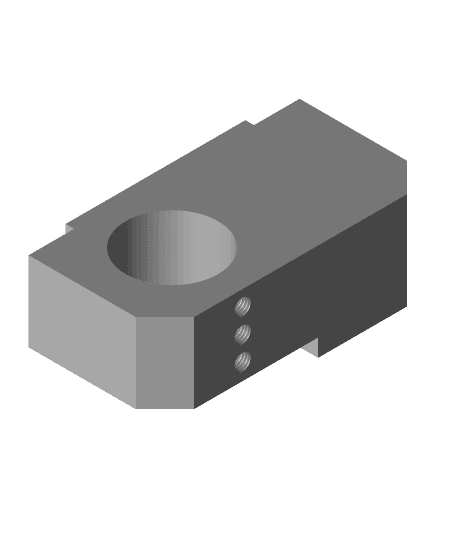
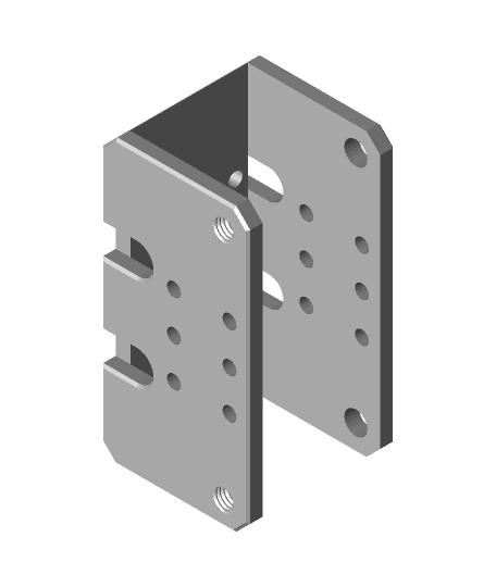
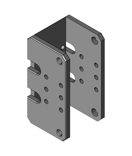
SolidCore CoreXY Hotend Mount.stl
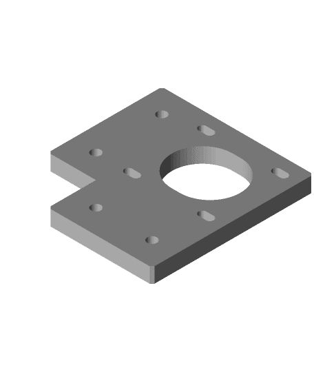
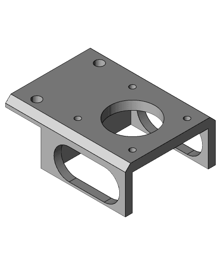
SolidCore CoreXY Motor Plate With 20mm Clearance Gates.stl
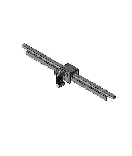
SolidCore CoreXY 3D Printer Y-Axis Assembly
SolidCore CoreXY Gantry
SolidCore CoreXY- VzBot 3D Printer Carriage-Gantry Mod
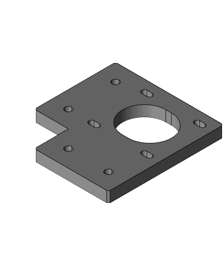
SolidCore CoreXY Motor Plate With 20mm Clearance Gates .step
SolidCore CoreXY- VzBot 3D Printer Carriage-Gantry Mod STP File
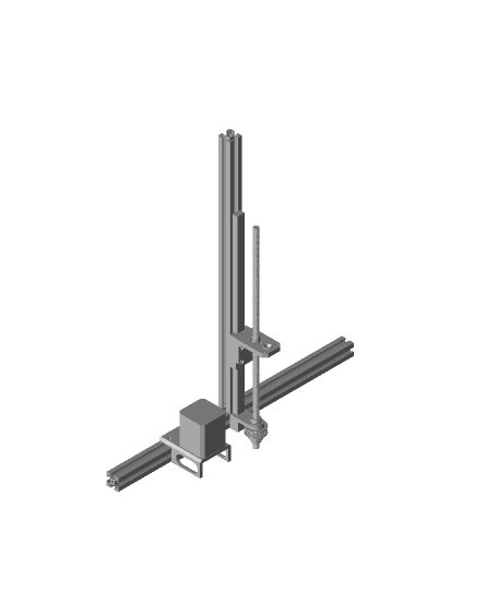
SolidCore CoreXY Z-Axis Design Belted Z-Three Point Leveling Mechanism
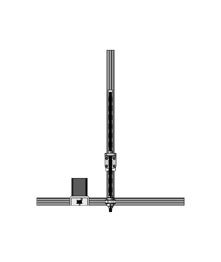
SolidCore CoreXY Z-Axis Design Belted Z-Three Point Leveling Mechanism
SolidCore CoreXY 3D Printer
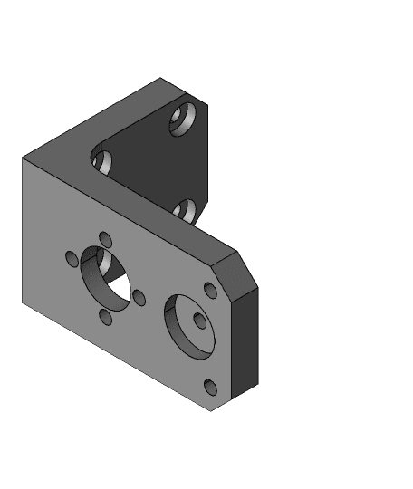
Nema 17 Triple Z Stepper Motor Mount SolidCore CoreXY STEP
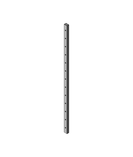
MGN12-H Linear Rail 400mm Long-3D Distributed.step
X-Carriage_Assembly_Single
X-Carriage_SolidCore_CoreXY_3D_Printer.stl
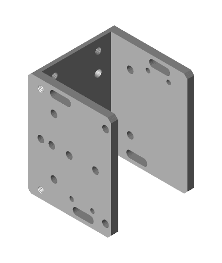
CoreXY Carriage.stl
CoreXY Carriage .step
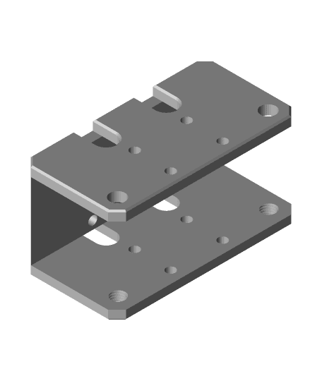
Y-Carriage Weight Reduced v2-SolidCore CoreXY.stl
Y-Carriage-with-belt-clamp-slots-Weight-Reduced-SolidCore-CoreXY-3D-Printer.stl
Documentation https://drive.google.com/drive/folders/1HQyc4OiMpGds7vOD8sf6P66I1bQqIA30?usp=sharing
Read Me https://docs.google.com/document/d/1iZ2HTbhTyqyrB8carmGXE6QQGxTL2o7xdminfGZprhc/edit?usp=sharing