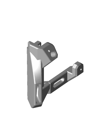
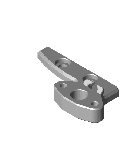
Mini Filament Sensor
Model originally uploaded to Thingiverse at https://www.thingiverse.com/thing:4598713.
Q: Why another filament sensor? A: Well, why not?
Q: What is wrong with a simple limit-switch one? A: Nothing. But if you need something else that adds very little drag on the filament and is dimensioned differently than a limit-switch, then this might be useful ...
The metal piece of a limit-switch is basically a spring and springs have the "feature" that the force they push back with increases as you push them away from their normal position. For a filament sensor that typically means that the limit-switch will be pushing your filament against a wall of your sensor body, causing drag en possibly erosion over time.
Magnets are like inverse springs: the force they exert gets lower the further you move the magnets apart. In the design here you can feel this very well: you feel the effort it takes to pull the magnets apart to get the holes - lined with PTFE tube - to align and allow the filament through, but when those holes do align, the magnets are so far apart that the force they exert is still sufficient to get them to move back together if there is no filament connecting the holes, but causes barely any drag on that filament ...
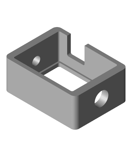
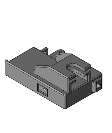
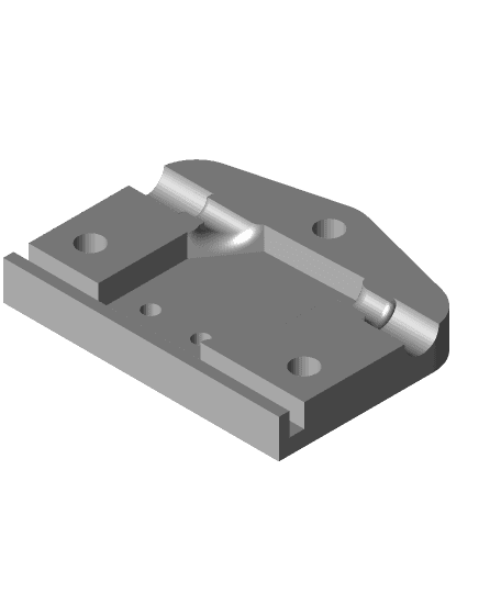
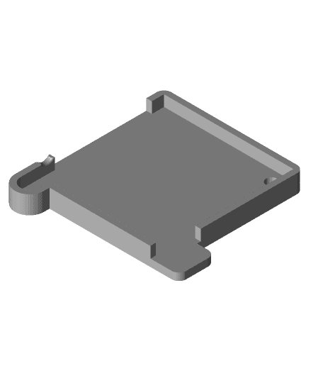
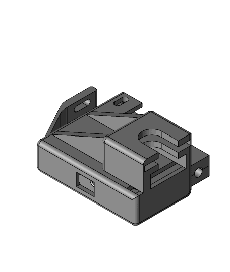
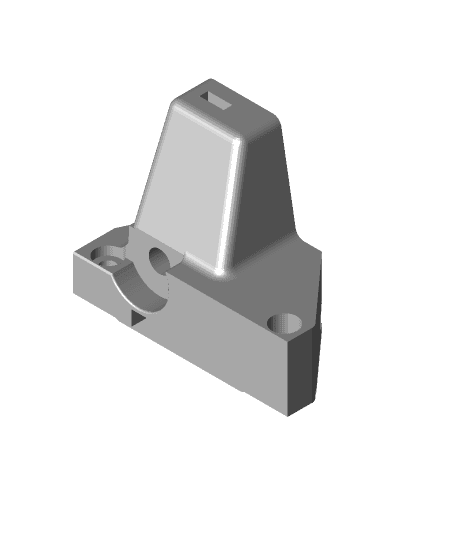
When printed in the provided position, no supports should be needed and the entire sensor prints as one. The second part is a mount, again not requiring supports in the given position. I do suggest using a raft (2mm extra sticking out under the part should be enough) to avoid that elephant's foot fuses the moving arm and body.
Once printed, there is some extra work to do:
-
Prepare 2 cylindrical 5mm diameter magnets (around 2-3mm thickness), by soldering a wire to each of them. The wire diameter including insulation should be less than 2mm. The wire used for the moving arm should be very flexible to avoid that it stops the arm from closing. This is also the reason for the somewhat weird wire path.
-
Rotate the arm so that you have access to the hole for the PTFE tube. Insert a piece of PTFE tube into the hole and use a cutter to cut it flush with the arm. Then do the same for the PTFE holes at both side in the body. Make sure that you do not push the PTFE tube in too deep: the arm should be able to move freely.
-
Take one of the magnets with the wire soldered to it. Insert the free end of the wire through the diam. 5mm hole of the main body, bending it so that it goes into the small 2x2mm hole moving it out through the bottom. Then push the attached magnet into that hole as far as you can (but don't overdo it).
-
Take the second magnet and again push the free end of the wire through the hole from the bottom of the arm up towards the "ditch" that can hold this wire. Then push the magnet into the opening in the arm. Lead it in this "ditch" under the "finger tip", turning around and then to the bottom of the arm, ending close to the other wire. As said, the intention of this path is to allow the arm to move as freely as possible despite this wire.
Improved_Version_Filament_Jam_and Runout_Sensor
DIY Filament Runout Sensor
.jpg&w=3840&q=75)
Universal Portable WiFi Filament Runout Sensor - RunoutAnywhere
Mini Temp & Humidity Sensor Stand
Latest All In One Filament Jam and Runout Sensor
Combined_Jam_and Runout_Sensor_Newest
.png&w=3840&q=75)
Runout En-Coder-Cube
Prusa Mini Extruder Section - BMG Version
CR6-SE Sherpa Mini Direct Drive Extruder Adapter — Updated
Manta MK2 Duct & Tool Head System
.png&w=3840&q=75)
Heated 3D Printer Filament Dry Box / Hot Box

Sphereical Surface Measure tool
Ender 5 Core XY with Linear Rails MK2

£80 Wide Angle + Night Vision Camera
Filament runout sensor switch & filament guide for IKEA LACK table
Combined Sensor - Filament Runout and Filament Jam

Mini Filament Spool Displays (MysticMesh3D)
Mini Filament Spool

LGX Lite Pro Filament Sensor