(V2) For BIQU B1 - DIY Enclosure - Remix of Prusa's V2 IKEA Lack Enclosure - with extra doors (opening on 3 sides)
byDesign8Studio.com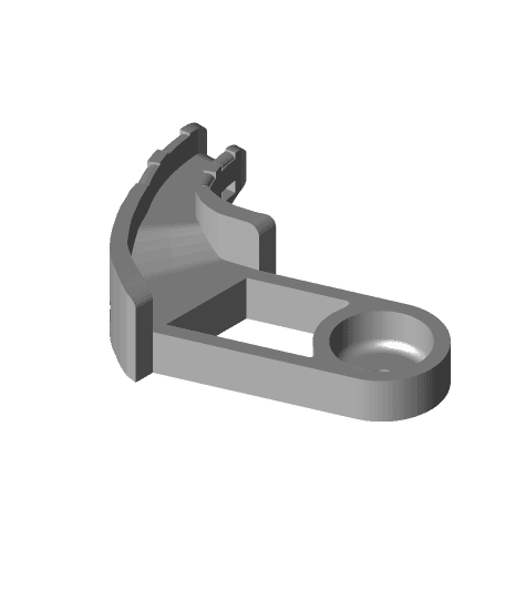
Model originally uploaded to Thingiverse at https://www.thingiverse.com/thing:5166976.
Heads up! This is the new, improved "v2" enclosure...If you were looking for the very popular, original "v1" enclosure, it's still available over here: https://www.thingiverse.com/thing:5137500
I created a fantastic ILLUSTRATED TUTORIAL - ASSEMBLY GUIDE for this DIY enclosure, downloadable for only $2.99 at https://design8studio.com/downloads/Please consider springing for the $3 in order to buy me a cookie in thanks, and get the illustrated assembly guide, gaining the easiest and best setup process for your enclosure! If you prefer not to, then you can still do things for free - see below.
. . .
If you're planning to make this, you can get a quick understanding of the reasons for a v2, and the differences it offers when compared to the v1, by reading the copy-and-paste (below) of a discussion from the comments on v1 — linked here: https://www.thingiverse.com/thing:5137500/comments#comment-6269801
Note: In the pic that shows my four enclosures, the lower two are Version 1, and the upper two are Version 2.
Why v2?OK, so pretty much everyone who makes the original Prusa-designed enclosure comments that it's wobbly, not stable, not as sturdy as they were expecting. I went into my v1 remix realizing that was a price of having an option to lift the whole thing off its base whenever needed. The "pro" is the opening. The "con" is the instability. But what if the door opening is big enough to slide a BIQU B1 in and out as needed, without lifting up the enclosure off its base? Well, with my design here, the opening is big enough, and the base can indeed be solidly "fixed" to the top, and thus you can gain the sturdiness that offers. Insertion of a B1 is as simple as leaning it back, sliding in, and then standing it up.
Q&AQuote from Thingiverse member Wilklersticks, who built my v1 enclosure design:
What are you doing to minimize the wobble? Parts fit together, but not snuggly enough to completely stabilize it.
My reply:
The lack of stability is an issue! It stems from original Prusa v1 design. It's seemingly a result of at least a couple of apparent design goals of the original Prusa v1 IKEA Lack enclosure. One is the option of being able to "lift" the whole enclosure up off the base, which has the top intentionally not secured to the base (!), and another is their desired "aesthetic" of clean smooth "lines" down the sides, thus only "gripping" the vertical Lack table legs from two sides instead of four sides.
Several thoughts on that: In their V2 design, they opted to secure the top to the base, and to have the top of the enclosure hinged, and I agree that the the fixed bottom is needed. I don't know that I agree with the need for a hinged top. If my B1's can be inserted and removed with a fixed base and without a hinged top, then I'm for that. (More on that below.) Also, they strengthened the door hinges by designing for long M3 screws to bolster the strength of the plastic, which I agree is majorly helpful. They also moved the door magnets into the hinge mechanism. (I'm OK with that.) However, they kept the design scheme (flaw?) of only attaching to two sides of the vertical table legs.
All that said, once you get your printer inside it and get your enclosure in position somewhere, then if you don't have to move it often or take the top off very often, you should be fine.
In my case, after having built three of my "v1" remix, and as I was about to start on a fourth one, I had a mishap in which one of my three fell, and hinges broke and corners broke. So, I decided [then] ... to do another remix, but this time based on a majorly revised version of [Prusa's] V2, borrowing the concepts I like and leaving out the ones I don't like. I also determined (just as Prusa did) to keep backward "compatibility" with as much of my V1 remix materials as they did for theirs, including same size of plexiglass panels.
[After quite a few iterations of design, prototyping, printing and testing...]
I was able to stay with vertical door magnet insertion on the bottom corners / hinges, but due to spacing restrictions I had to switch to horizontal door magnet insertion on the top corners / hinges.
Regarding whether a BIQU B1 can be inserted and removed with a fixed base and without a hinged top: they can indeed!
So I now have two "v1" enclosures and will have two "v2" enclosures. Hopefully you get great service out of yours. Please post your "make" and upload pics!
SOME DETAILSI am a big fan of the BIQU B1. Of the seven 3D printers I currently own, four are B1's, and I have a BIQU B1 SE Plus on order. As you may know, a B1 is too tall to fit in the Prusa designed IKEA Lack enclosure (version 1) and their version 2 (which needs more height / headroom because of their multi-material add-on) costs a whopping 200 hours of print time because they decided to gain the extra headroom by printing plastic. I thought, "The IKEA Lack tables are only $9.99. I'll use an extra set of legs (turned side ways) to get the extra height." In short, it works, and the resulting enclosure holds a BIQU B1 nicely!
One minor caveat: just as many using the Prusa enclosure have had to print a new design of "heater bed wire strain relief part" with a 90 degree bend, in order to keep the heater bed wires from bumping the back pane of acrylic, this design also calls for that, and the good news is that my remix here already includes a part custom designed just for the BIQU B1. It's a drop-in replacement. Just use three zip ties to secure your heater bed wiring into the new part.
So, without further ado, here is...
VERSION 2 - DIY Lack table enclosure for BIQU B1 PARTS FOR PRINTINGThis revision requires supports being turned on with the "bottom corners" sheet and the "top corners" sheet! No fiddly settings. Just switch on "Supports" in Cura or whichever slicer you have. I like Cura's tree supports! They are easier to remove!
Just as with the Prusa design, most of the printed parts are organized into sheets of multiple parts that are all designed to fit on the print bed of a BIQU B1. Those sheets are:
• Bottom Corners and Back Bushings.stl • Top-Corners.stl • Top-Extenders.stl • Door-Knob-(x3)-and-Cable-Clips-(x10).stl
Additional parts that are not ganged up on a sheet with others:
• BIQU-B1-ac-heater-wire-redirect-strain-relief-bracket.stl
The main reason the strain relief part is by itself is so you can more easily print it in PETG, which I did and advise you do, because of its exposure to heat from the print bed. PLA might be fine, but you have trouble with deforming, upgrade to PETG.
Note on the "Back Bushings" — you're probably wondering what those are... My design allows the one solid side (without doors) to be either in back or on either the left or the right side. Depending on where you place that panel, you might need your "ac power cord hole" on one side or the other. So, this design provides "AC power cord holes" on both sides. The parts list includes two plugs to fill those two holes (plugs that Prusa calls "bushings," so I am too). They can be clamped around the already-inserted AC power cord, and slid in place. The side without a power cord will have a hole in the plug unless you plug the hole. (These are the jokes, people.)
Note on “door handles and doorstops” — Although Prusa’s V2 design seems to not have their V1 door handles and doorstops in the middle where the doors meet, I'm leaving my V1 part sheet (with those on it), in case you want door handles, or in case the doors don't seem to stop in exactly the right place and you decide to use the V1 doorstops. The trick of getting the doors to stop based on bumping what might be called "hinge stop blocks" (where the magnets are installed in the hinges) will depend somewhat on printer calibration and whether your acrylic sheets are exactly the right thickness (which if too thick it can bulge a hinge a bit). My experience is that most stock B1's come "out of the box" over-extruding a little. I’ve tried to err on the side of the doors closing a teensy bit inside as opposed to being still open a bit when they hit. This is a work in progress, and I will be responsive to feedback in the comments. In the meantime, likely it's easier to shim than to trim.
NON-PRINTED PARTS LISTHARDWARE NOTE Four long screws are called for, longer than any used in the Prusa design, because of accommodating the additional headroom. These need to be 4" long (1/4" in diameter, or #12). An affordable way to source what you need is to buy lag screws from your local hardware / home improvement store. My design enlarged and deepened the "countersink" opening in the printed plastic part so that not only can the thicker hex head of a lag screw be fully countersunk, but also a socket head should fit in there around it to ratchet tighten the hex screw down. Of course if you have some #12 x 4" pan head screws, you could use them.
Also note regarding product links (below) to items I bought and used: they may be affiliate links if that option exists.
Parts List
• 2× IKEA Lack tables — https://www.ikea.com/us/en/p/lack-side-table-black-20011408/
(or 3x IKEA Lack tables if you want your enclosure to have its own “floor stand,” i.e. not placed on a shelf, table, or desk. The third table could only have its legs used. Be creative on what you could do with the top. Or perhaps you want to build the third table as normal, and set your enclosure on it, but not attach it. It could later be moved to a shelf etc, and the table used separately.)
• 1 acrylic pane, 3mm thick, 440 mm x 440 mm • 6 acrylic panes, 3mm thick, 220 mm x 440 mm
Notes: If you already have acrylic doors and window from a V1 enclosure, those can be reused on the v2. A sheet that is bought at 36"x72" is large enough for two enclosures to have all their doors and windows, and naturally a 36"x36" is large enough for one full enclosure’s set.
Here is a link to Lowe’s 36"x72" sheet: https://www.lowes.com/pd/OPTIX-0-118-in-T-x-36-in-W-x-72-in-L-Clear-Acrylic-Sheet/3140717
Also note that apparently buying 1/8" thick acrylic sheet is really close to 3mm, but not exactly the same, and it's what I bought, and it explains why my hinges bulged out a teensy bit. I may work to address this with two hinge design choices. For now the variance seems to be within tolerances.
• 24x Neodymium magnets — 20mm x 6mm x 2mm.
Notes: Magnets sold in this shape are often actually slightly smaller, such as 19mm x 4.75mm x 1.75mm, and that's OK. There are 8 magnets per door, so a total of 24 if you go with the plan for 3 doors.
These are the magnets I bought and used: https://www.amazon.com/gp/product/B088YYC2N1/ref=as_li_ss_tl?ie=UTF8&psc=1&linkCode=sl1&tag=httpdougjosne-20&linkId=eee25801aefa71b8ddb238cc7a80204c&language=en_US Deryun 60Pack Rectangular Magnets
Fasteners
• 4x Lag screws, 1/4” x 4" (or pan head screws, #12 x 4") Notes: these are for attaching each Top Corner and matching Top Extender “set” to the tabletop.
• 4x Pan head screws #12 x 2" Notes: these are for attaching each Bottom Corner to the table base. I used pan head screws designed for "metal" use; an affordable option.
• 8x Countersunk head (or pan head) Phillips screws #8 x 3" / course-thread drywall screws Notes: these are for attaching the horizontally positioned table legs to tabletop. I used #8 x 3" black course-thread dry wall screws.
• 40x Countersunk head Phillips screws #6 x 1 1/4" / course-thread drywall screws Notes: these are both for attaching the horizontally positioned table legs to the Top Extenders (takes 8x), and for attaching the vertically positioned table legs to the Top Corners and Bottom Corners (takes 32x). I used #6 x 1 1/4" black course-thread dry wall screws.
• 6× Pan (hex) head metric screws M3×16 Notes: these are for attaching top hinges to Top Corners.
• 6× Pan (hex) head metric screws M3×25 -OR- • 6× Pan (hex) head metric screws M3×10 AND 6× pan (hex) head metric screws M3×12 Notes: these are for attaching bottom hinges to Bottom Corners. Can be two shorter screws from bottom and top, or one longer screw from bottom.
Optional but recommended:
• Smoke Alarm (battery operated) (suggestion links below) • LED strip, 5'-7" length (recommended: warm white "5050" LEDs) (suggestion links below)
ASSEMBLY INSTRUCTIONS(1.) Attach hinges to their corner prints using M3 screws, and insert/glue the magnets into the hinges and into the corner parts.
1a. Bottom hinges are taller, and go with the bottom corners, which are also taller. For these, either use two short M3 diameter screws (from both the top and bottom) or a long one from the bottom. If using two, the top one can be M3x10mm and the bottom one can be M3x12mm. If using one long screw, it should be between M3x22mm and M3x25mm. Make sure that the screw tip / screw head is not proud of the corner piece on either top or bottom.
1b. Magnets for bottom hinges and Bottom Corners are inserted vertically. Be sure to install your magnets oriented the right way, so they are attracting and not repelling. After inserting the magnets, add a couple drops of super glue and let it run down around the magnet, locking it in.
These are the magnets I bought and used: https://www.amazon.com/gp/product/B088YYC2N1/ref=as_li_ss_tl?ie=UTF8&psc=1&linkCode=sl1&tag=httpdougjosne-20&linkId=eee25801aefa71b8ddb238cc7a80204c&language=en_US Deryun 60Pack Rectangular Magnets
The original Prusa-spec'd magnet was 20mm x 6mm x 2mm. Magnets sold in this size class are often actually slightly smaller, such as 19mm x 4.75mm x 1.75mm, and that's OK.
1c. Top hinges are shorter, and go with the top corners, which are shorter. The screw(s) to attach the top hinges are M3 x 16mm.
1d. Magnets for top hinges and Top Corners are inserted horizontally. Be sure to insert your magnets oriented the right way, so they are attracting and not repelling. After inserting the magnets, add a couple drops of super glue and let it run down around the magnet, locking it in.
Again, be sure to insert your magnets the right way. Sorry, the top hinges require the magnets inserted sideways. It could not be helped if I was to preserve usability of acrylic panels already cut to the original dimensions.
(2.) Attach printed corners to IKEA tabletops (one tabletop for the enclosure’s top and another for its base).
2a. First the bottom. Place an IKEA tabletop "face up" (black side facing up). Place the printed bottom corners (with hinges already attached and magnets already installed, see step #1) at each corner, aligned exactly against the edges of the tabletop. (I like to clamp them in place so they don't wander while I'm screwing them in.) Pre-drilling helps. Screws for attaching them can either be #12 x 2" pan head screws, or even 2" long #6 course-thread drywall screws. Don't get crazy with tightening, as there is not a lot of wood in the IKEA stuff, although I think what little there is… is concentrated in tabletop corners and leg ends. Repeat the above at all four corners, and set the bottom aside.
2b. Now the top. Place another IKEA tabletop "face down" (MDF/wood side facing up). Place the printed top extenders at each corner, with their teardrop shaped keys facing you (facing upwards). The top corners have teardrop shaped keyholes in them to help you see which way they go. This allows "indexing" somewhat. Be sure the top corners already have hinges attached and magnets already installed. Use a 4" lag screw (1/4” in diameter, or #12 size) to attach the top corners to the top extenders, and both of those printed parts to the tabletop. Repeat x4 at each corner.
(3.) Attach both sets of IKEA legs to the TOP... (the base is not needed at this time).
3a. IKEA legs attached horizontally first. Four (4) IKEA legs go in horizontally (to extend the height). These go in between the "Top Extenders" and then are attached to them by screws (and screwed to tabletop). This is designed for a snug fit, so have a rubber mallet on hand in case a few love taps are needed. These can be attached with whatever screws you have. Vertically, to attach these legs to the tabletop, I used black, course-thread, drywall screws about 3" long (#8 x 3"). Bear in mind, there’s more wood inside one end of the leg with a factory-drilled hole in its end. The wood at the other end is very thin, so pre-drilling the IKEA legs with a 1/8” bit is strongly recommended, and stay close to the edge if you hope to hit wood. Don’t over tighten!
Horizontally, I then used black, course-thread, drywall screws about 1 1/4" long (#6 x 1¼”) to attach them sideways to the corner extenders. Pre-drilling here is optional, but again, don’t over tighten!
3b. Then, four (4) more IKEA legs go in vertically, and here's where you gain extra rigidity and strength because my design has screws going in four sides instead of only two. Again here I used black course-thread drywall screws about 1¼" long (#6 x 1¼").
(4.) Install L.E.D. light strip (optional, but recommended) — on horizontally placed legs (or underside of top)
L.E.D. NOTES — “THE BETTER TO SEE YOU WITH”
Among the advantages of using the additional set of table legs to gain the needed extra headroom is that those legs provide a great place to attach LED lights. I like this placement better than on the underside of the top, because a continuous strip of lights can be installed without having to cut it into separate pieces (that would then need re-wired to stay attached to each other).
Below are several tips about LEDs:
Reusing leftover LEDs is great: If you have leftovers from some prior install of an LED strip of the kind that accepted color change commands from a controller with remote, and you just have some strip left with no more controller or remote, those leftovers can definitely be used for this kind of thing, and for me, I really just want nice bright white light in there, not a lot of crazy colors. I need to see!
Reusing old AC power adapter — match volts and exceed amps: This is also a great way to make use of your litany of mysterious AC adapters laying around your house from who knows what that is no longer in use. Any AC adapter that matches the right voltage, for example if the LED light strip was 12v then the adapter should be 12v, and also which is rated at or above the needed amps, will work. (Any adapter that's rated for at or above 3 amps or more should be fine, 5 amps would be ideal). Don't worry about it allowing higher amps. The AC adapter does not force the higher amps, it just offers them if the device wants to draw them. Any attempt to under power is where problems arise — the adapter can overheat. Don't try to power this many lights with only a 1-amp or 2-amp adapter! Again, 5+ amps is ideal, and 3 amps seems to work OK too.
Length of LED strip: I've found that somewhere around 5'-7" of LED strip length is enough (about perfect) to get all the way around. If you are coming up short, then simply choose one side to leave out, or not completely cover.
How to get a leftover strip of LED to burn all white: you want all three colors of RGB to be fully powered, and if it is a "warm white" version with an additional set of warm white LEDs, then that extra “line” needs full power too. To accomplish this (full power on all wires) you simply connect your "hot" (live or "+") wire to the "12v" wire on the lights (it will be labeled as such right on the LED strand, every few inches or so) and then connect the neutral or "-" wire to all the other leads. That gets full power to all, and you get white light.
Warm white or cool? I noticed the strips that don't say "warm white" tend to have a slight bluish tint that may or may not bother you. I did my first one with warm white, and liked it a lot, and then I wanted all of my enclosures the same for consistency. I personally prefer the warm white. I think name brand is not as important as voltage and right color and it being decent quality. There's a bunch of name brands on Amazon, etc. A good type to get, whether warm white or not, is “5050.”
More LED install details are below, in the “product links” section (with both tools and supplies) with more info on how to connect LEDs, as well as some links to good smoke alarms. Speaking of which….
(5.) Install Smoke Alarm (optional, but recommended) — underside of top. Better safe than sorry. I advise to install smoke detectors in all enclosures. Further down are some item links for consideration. If your house is multistory or your printers are in a basement, consider the kind that communicate with each other, so if one goes off, they all do, and announce where the issue is. They cost more, but are advisable.
(6.) Set the one 440mm x 440mm acrylic sheet into the top (which is still upside down). Regarding your 3mm (1/8") thick plexiglass panes, on the side of the top that is without hinges insert your one solid acrylic window pane (440mm x 440mm) into its holders. Speaking of the acrylic panels, all are to be sized/cut exactly as with the Prusa v1 and/or v2 Lack table enclosure (one 440mm x 440mm for any solid panes with no door, and two 220mm x 440mm panes for where doors are called for (total of 6 for 3 sides with doors). (NOTE: At this time there is no need yet to insert the other acrylic sheets (240mm x 440mm) for the doors. Those can all be threaded in later, after the bottom is attached, by swinging the hinges open for access.)
(7.) Attach the Base to the vertical legs. Flip the base over, upside down, and set it onto the vertical legs, while also threading it onto the acrylic sheet (440mm x 440mm). Tap it down firmly with a rubber mallet. Use screws to attach each "Bottom Corner" to each of the vertical legs. Again, I used black, course-thread, drywall screws about 1¼" long (#6 x 1¼").
(8.) Insert the acrylic doors (220mm x 440mm) on three sides. Spin the hinges open about 45 degrees each, and thread each acrylic door in … first into either the lower or upper hinge, and then into the other hinge, and then gently tap with a rubber mallet to seat it in place.
(9.) Flip the enclosure upright, and insert your cables and the 3D-printed Back Bushings in the openings. Insert your printer’s AC power cable through whichever of the two back openings you desire, and then clamp the two sides of a Back Bushing (aka cable plug) around it, and slide it in. If you have LED power wires they could also be routed along with the power cable. Use the other back bushing to fill the unused hole on the other side.
ADDITIONAL NOTES AND PRODUCT LINKSBUILD VOLUME Z HEIGHT REMAINS INTACT
One other note on the extra enclosure height needed to accommodate a B1: The B1's advertised build volume height is 270 mm. In my B1 inside this enclosure, I'm able to get 270 mm of Z height. So if you're concerned about it, I'm not experiencing any loss of build volume height.
DRY BOX OR TOP-MOUNTED SPOOL HOLDER?
Finally, regarding filament placement: remember that the Prusa design offers an adjustable filament spool holder for the top. I'm not using that personally, because instead I will be using my existing, excellent filament dry box design, which is another remix I plan to post soon. If you want the adjustable filament spool holder for the top, just head over to the original Prusa design and grab it.
Oh, and as promised...
HOW I PRINT MUCH QUICKER WITH STOCK HARDWARE
Here are the two videos that give details on how I print much faster with stock hardware (changes to slicer settings only):
"BIG nozzles - HOW they (can) make your 3D prints STRONGER" by CNC Kitchen Nov 23, 2019 https://www.youtube.com/watch?v=QfASQ8VgAbk&t=670s
"Print FASTER: Tuned Profiles or Drilled Nozzles?" by Thomas Sanladerer Sep 25, 2020 https://www.youtube.com/watch?v=6fPq8vUS38Y
Change Log2021-12-22 12:50pm (Eastern) - added link to ILLUSTRATED TUTORIAL - ASSEMBLY DIRECTIONS (PDF)
2021-12-19 at 7:23 AM (Eastern) - updated the Zip file of STL single pieces (only for if you need to reprint something)
2021-12-19 at 7:23 AM (Eastern) - slightly revised "Top Corners" and "Top Corner Extenders," to get closer to perfection on bolt hole alignment with factory pre-drilled hole on IKEA table top (underside).
2021-12-18 at 3:40 AM (Eastern) - updated the Zip file of STL single pieces (only for if you need to reprint something)
2021-12-18 at 3:30 AM (Eastern) - slightly revised "Top Corners" and "Top Corner Extenders," to get closer to perfection on bolt hole alignment with factory pre-drilled hole on IKEA table top (underside).
2021-12-17 at 11:10 PM (Eastern) - uploaded a Zip file of STL single pieces (only for if you need to reprint something)
2021-12-17 at 9:55 PM (Eastern) - slightly revised "Bottom Corners" and "Top Corners," to get closer to perfection on stopping point for the door hinge action.