
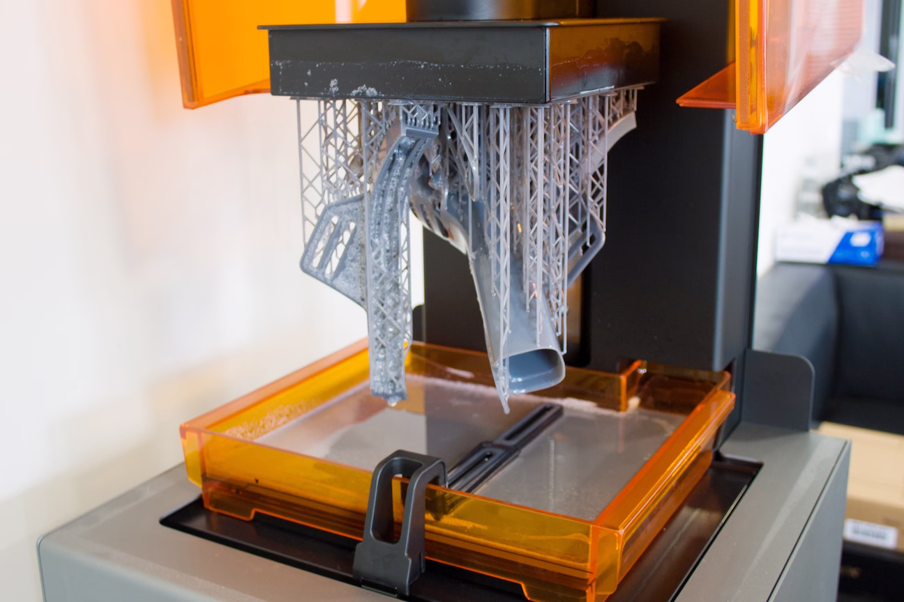
Stereolithography (SLA) is a 3D printing process that uses a UV laser to cure liquid photopolymer resin into solid plastic. By tracing a laser beam across a resin vat, it hardens the liquid layer by layer with extreme precision, allowing for far more intricate geometries than traditional filament-based printing. This technology is most known for its smooth surface finish and near-invisible layer lines. Because of this high resolution, SLA is the industry standard for detailed work like jewelry, dental models, and professional-grade miniatures.

If you’re looking for ultra-smooth surfaces, intricate details, and realistic prototypes, SLA printing is a powerful choice. Some of the best applications include:
Highly Detailed Miniatures
Captures tiny accessories and sharp textures, even on small scales.
Lifelike Figurines
Renders realistic facial features and smooth skin textures without visible layer lines.
Jewelry Prototypes
Print intricate ring settings and fine engravings with stunning clarity.
Master Patterns for Molding
High-resolution SLA master parts to create silicone molds for casting.
Functional Prototypes
Smooth finish and tight tolerances needed to simulate injection-molded parts for professional prototyping.
SLA is a go-to technology for any project requiring precision, smoothness, and intricate detailing.
Materials

High Detail Plastic
A high-detail gray resin optimized for tabletop gaming miniatures, figurines, and collectibles.
TGM-7 combines a hard, smooth surface with balanced toughness and flexibility.
The build platform lowers into a liquid resin tank with a tiny gap at the bottom.
A UV laser traces the layer cross-section to harden the liquid resin into solid plastic.
The platform lifts to peel the cured layer and allow fresh resin to flow beneath it.
The platform returns to build height and the laser bonds the next layer to the previous one.
Once printing is complete, remove supports and UV-cure the finished part.
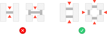
Design guidelines
±0.2% (with a lower limit of ±0.2 mm)
x
x
x
x
x
x
x
x
x
x
x
x
x
x
x
x
x
x
x
x
x
x
x
x
x
x
x
x
x
x
x
x
Lorem ipsum dolor sit amet, consectetur adipiscing elit, sed do eiusmod tempor incididunt ut labore et dolore magna aliqua. Ut enim ad minim veniam, quis nostrud exercitation ullamco laboris nisi ut aliquip ex ea commodo consequat. Duis aute irure dolor in reprehenderit in voluptate velit esse cillum dolore eu fugiat nulla pariatur.


