What is Material Jetting (MJP) 3D Printing?

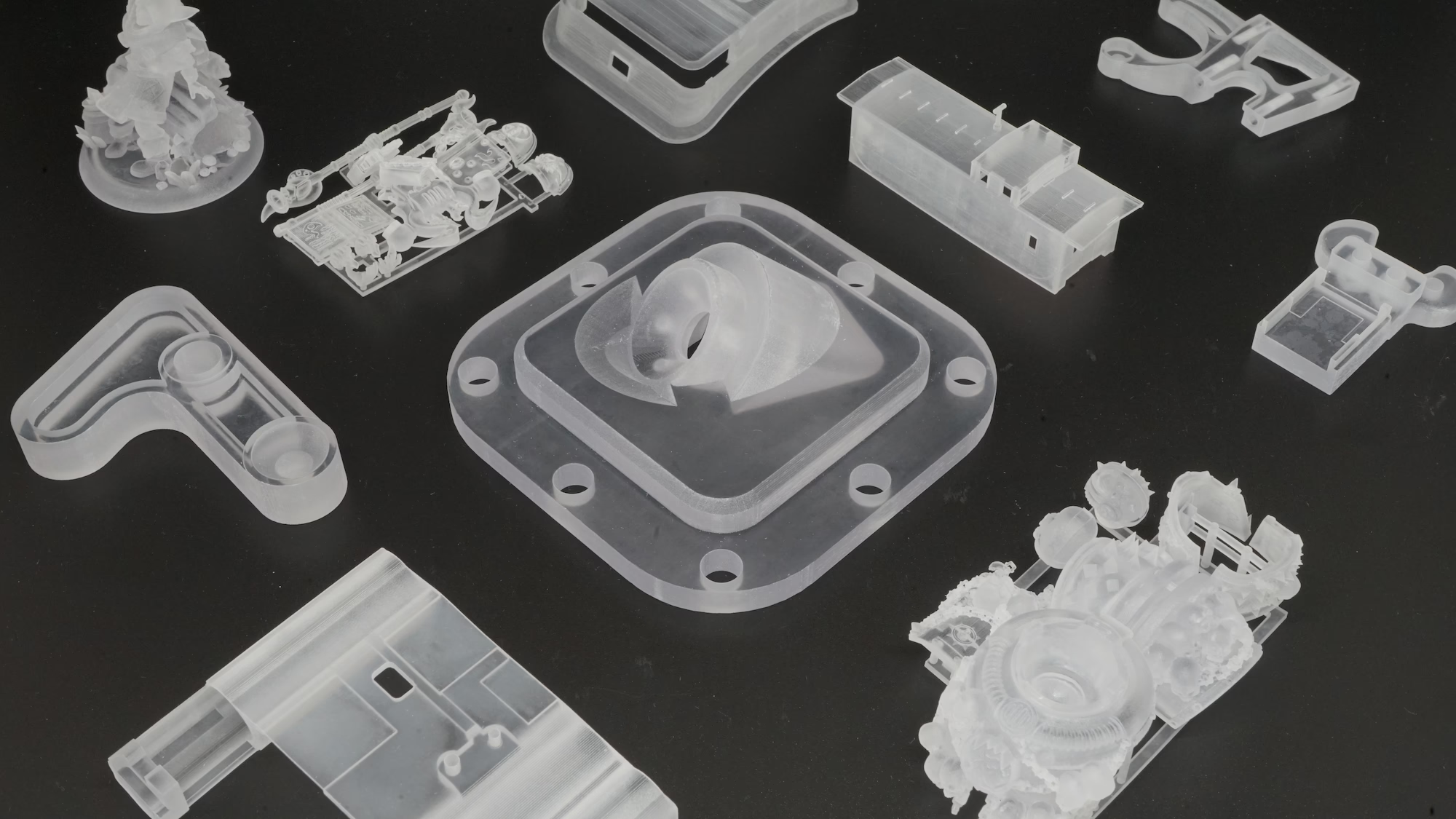
MJP is an acrylic material capable of extremely high detail and is a popular choice for hobbyists creating scale models, miniature sets, and other decorative products and is previously known as Fine Detail Plastic.

What can you print with MJP?

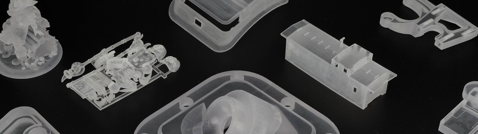
If you’re looking for ultra-smooth surfaces, intricate details, and realistic prototypes, MJP printing is a powerful choice. Some of the best applications include:

No Support Structures Needed

Unlike SLA or FDM, MJP naturally supports overhangs by encasing the model in wax during printing.

Highly Detailed Figurines & Miniatures

Capture lifelike details with precision.

Jewelry Prototypes

Print intricate ring settings and fine engravings with stunning clarity.

Architectural Models

Bring scaled designs to life with high-resolution accuracy.

Medical & Dental Models

Create detailed, realistic anatomical prototypes for study and education.

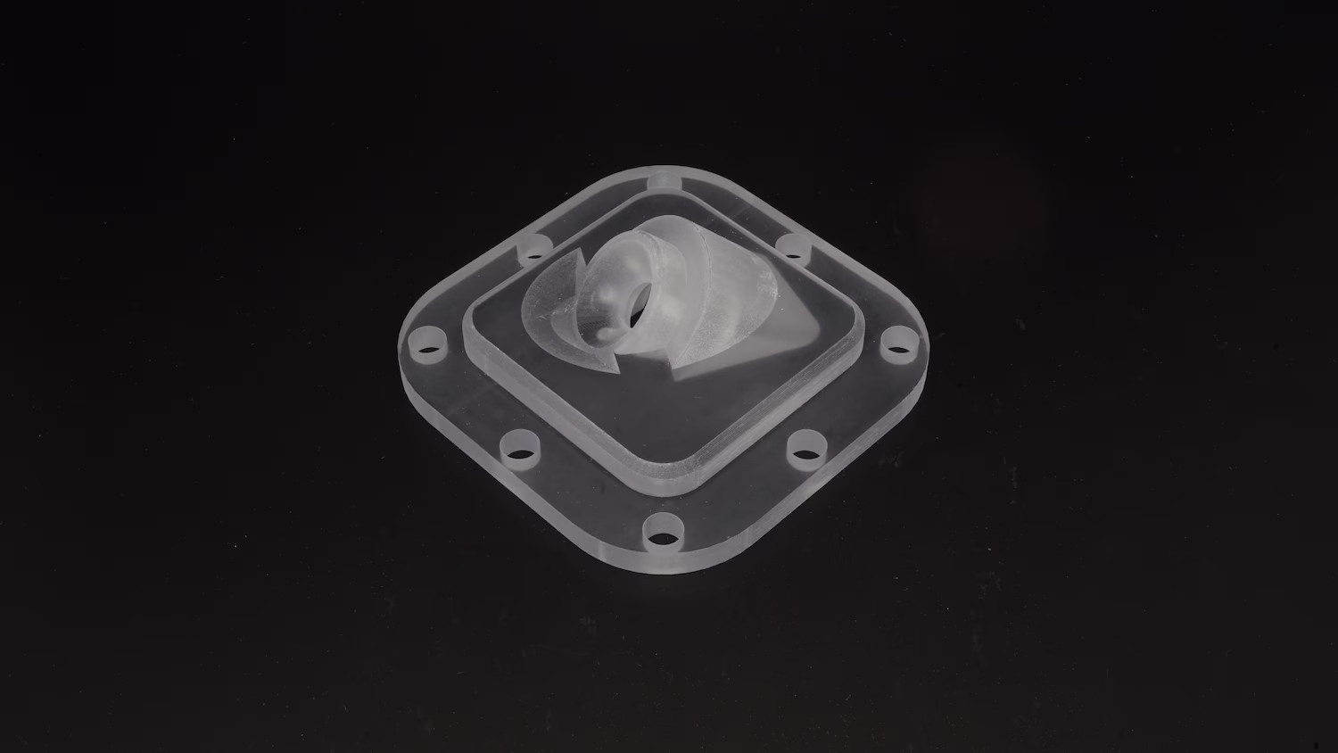
Product & Engineering Prototypes

Test ergonomics and fine-tuned features before full production.

MJP is a go-to technology for any project requiring precision, smoothness, and intricate detailing.

Materials

Full-color Nylon

Versatile & Strong

A highly durable nylon plastic that can be used for prototyping and end-use parts.

  • Strong and impact-resistant
  • Flexible when printed thin, rigid when printed thick
  • Available in multiple dyed colors

Design guidelines

Bounding box
i

The bounding box is a 3D imaginary outline of a box that encloses the smallest area occupied by your model. Your model must be within the minimum and maximum bounding box sizes. If the size of the model is close to the maximum bounding box, then the printing orientation will be restricted.

Max. bounding box

x
x

Min. bounding box

x
x

Walls
i

A supported wall is connected at least on two sides of the wall, while an unsupported wall is connected only on one side of the wall. Walls that do not meet the minimum requirements may not survive printing and cleaning processes. Additionally, models may still be rejected based on the wall geometry of the model. Please consider the size of your model and reinforce the walls or add support structures as needed as minimum guidelines will not always be adequate for large models.

Supported walls

x
x

Unsupported walls

x
x

Wires
i

A wire is a circular, rectangular or even triangular feature that is thinner in its unconnected directions than its length. A supported wire is connected at least on two sides of the model, while an unsupported wire is connected on one side of the model. Wires that do not meet the minimum requirements may not survive printing and cleaning processes. Additionally, models may still be rejected based on the wire geometry of the model. Please consider the size of your model and reinforce the wires or add support structures as needed as minimum guidelines will not always be adequate for large models.

an icon depicting guidelines for supported wires
Supported wires

x
x

an icon depicting guidelines for unsupported wires
Unsupported wires

x
x

Details
i

For text, the ratio between width and depth, should be 1:1 and sans-serif fonts are preferred for line weight consistency.

an icon depicting guidelines for embossed details
Embossed Details

x
x

an icon depicting guidelines for engraved details
Engraved Details

x
x

Clearance
i

Clearance is the space between two individual parts in a model. If the space among the individual parts do not meet the minimum clearance, then parts can fuse together or can be difficult to clean. This is important for movable pieces like hinges, gears, etc.

Minimum

x
x

Sprues
i

Sprues are wires that keep two or more parts together. Parts should be connected with a minimum of two sprues each. Please consider the size of your sprues and increase them as needed as minimum guidelines will not always be adequate for large models. If the sprues are within the guidelines and are broken, but there is no damage to your model, we will still ship them as is.

an icon depicting guidelines for sprues

x
x

Interlocking & Enclosed parts
i

The bounding box is a 3D imaginary outline of a box that encloses the smallest area occupied by your model. Your model must be within the minimum and maximum bounding box sizes. If the size of the model is close to the maximum bounding box, then the printing orientation will be restricted.

Interlocking

x
x

Enclosed

x
x

Escape holes
i

A wire is a circular, rectangular or even triangular feature that is thinner in its unconnected directions than its length. A supported wire is connected at least on two sides of the model, while an unsupported wire is connected on one side of the model. Wires that do not meet the minimum requirements may not survive printing and cleaning processes. Additionally, models may still be rejected based on the wire geometry of the model. Please consider the size of your model and reinforce the wires or add support structures as needed as minimum guidelines will not always be adequate for large models.

Single Escape hole diameter

x
x

Multiple Escape hole diameter

x
x

Accuracy
i

The bounding box is a 3D imaginary outline of a box that encloses the smallest area occupied by your model. Your model must be within the minimum and maximum bounding box sizes. If the size of the model is close to the maximum bounding box, then the printing orientation will be restricted.

x
x