Multi Jet Fusion (MJF) is an advanced powder-based 3D printing technology that creates strong, precise, and functional parts at high speeds. Unlike other 3D printing methods, MJF uses an inkjet array to apply fusing and detailing agents onto a powdered material layer, which is then solidified with thermal heat.
MJF printing is versatile, making it an excellent choice for functional, high-performance parts. Some great use cases include:
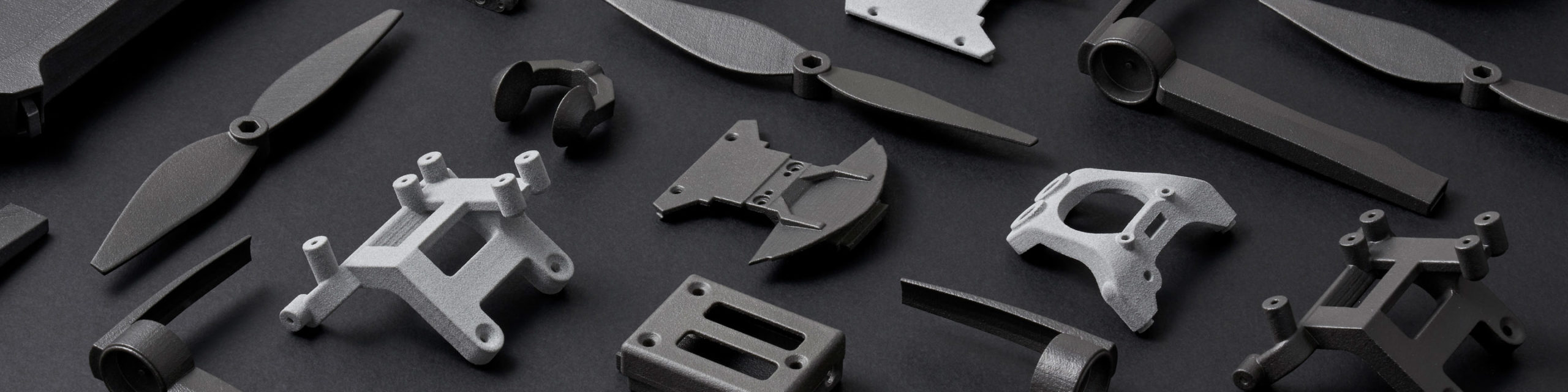
End-Use Parts & Mechanical Components
MJF parts are strong, durable, and reliable, making them perfect for structural elements, mounts, and enclosures
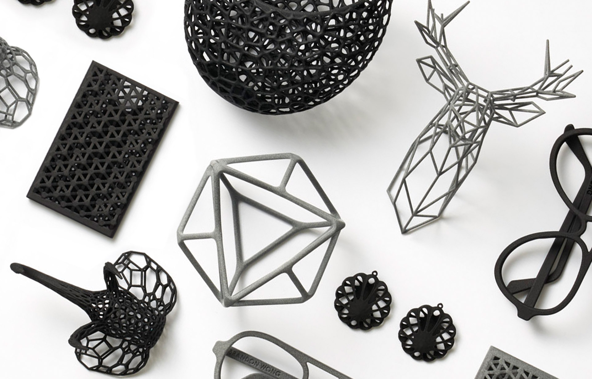
Full-Color Prototypes & Models
Unlike many other printing methods, MJF supports color 3D printing, making it ideal for visual models, branding, and customization
Automotive & Aerospace Parts
MJF offers heat-resistant, stiff materials, great for high-stress applications
Medical Devices & Wearables
MJF’s biocompatible materials make it suitable for custom medical solutions and prosthetics
If you need high-quality, strong, and customizable parts, MJF is a powerful 3D printing solution.
Materials
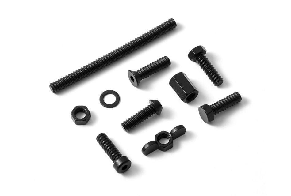
High-Strength & Durable
A tough, impact-resistant nylon plastic commonly used for:
- End-use products and engineering parts
- Structural components requiring stiffness and durability
- Available in grey or black finish

Strong & Vibrant
A versatile, durable nylon plastic with full-color printing capabilities, perfect for:
- Industrial parts, functional goods, and branding applications
- Mechanical components with structural strength
- Multi-color models based on texture files
Full-color models require a texture file for accurate printing.

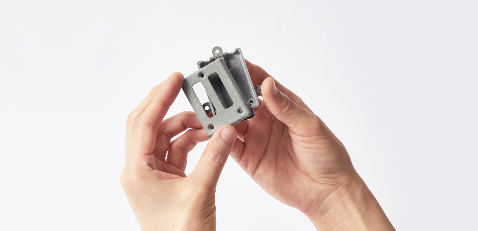
Extra Stiff & Stable
A nylon composite infused with 40% glass beads, designed for:
- Increased stiffness and dimensional stability
- Reduced warping and shrinkage
- Available in grey or black finish
A thin layer of powder is spread over the print bed.
An inkjet array deposits fusing and detailing agents onto the powder in specific areas.
Thermal heat fuses the layers together, bonding them for strength.
The process repeats layer by layer until the part is fully built.
Excess powder is removed, and post-processing options like smoothing, dyeing, and polishing can be applied.
Design guidelines
Natural: ± 0.2 mm ± 0.5% of the length
Smooth: ± 0.4% (with a lower limit of ±0.2 mm)
For example: a product with dimensions of 50 x 50 x 100 mm can be 0.2 mm + 0.005*100 mm = 0.7 mm bigger or smaller in any direction.
Natural: ± 0.38mm in the XY and ±0.5mm in the Z
Smooth: ± .45mm in the XY and ± .52mm in the Z
± 0.2 mm ± 0.5% of the length
x
x
x
x
x
x
x
x
x
x
x
x
x
x
x
x
x
x
x
x
x
x
x
x
x
x
x
x
x
x
x
x
Lorem ipsum dolor sit amet, consectetur adipiscing elit, sed do eiusmod tempor incididunt ut labore et dolore magna aliqua. Ut enim ad minim veniam, quis nostrud exercitation ullamco laboris nisi ut aliquip ex ea commodo consequat. Duis aute irure dolor in reprehenderit in voluptate velit esse cillum dolore eu fugiat nulla pariatur.


