
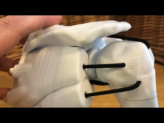


Dynamic Shoulder Rotator Cuff Education Model
This dynamic shoulder rotator cuff model is designed specifically to simulate shoulder dislocations and treatments but it can be used for a range of clinical education applications.
See here for video: https://youtu.be/GVXmNw9ABjo
In this model, the humerus is held in place by a series of elastic cords that simulate the pull of rotator cuff muscles and ligaments. Tension on the elastics can be adjusted to simulate variability in rotator cuff integrity and support around the glenohumeral joint.
The six anchor points between the scapular assembly and head of humerus represent the major components of the rotator cuff (subscapularis, infraspinatus, supraspinatus, teres minor, and approximations of the anterior and posterior glenohumeral ligaments)
Assembly requires six M6 barrel adjustors and approximately 1m of elastic cord or strap. Additionally, you may choose to use crimps to secure the ends of the elastic.
The M6 barrel adjustors are commonly used in bicycles to adjust cable tension of gear derailleurs. They can be purchased from a bike store or online.
This model shown uses two types of elastic, 1/4” (6mm) wide elastic band, and 1/8” (3mm) diameter elastic cord. While both will work fine, the cord is easier to work with during assembly.
Print the head and shaft of humerus as oriented. Print the scapular assembly as oriented but raise it above the surface of the bed approximately 3mm and build supports up to bottom surfaces and overhangs. It is important that the glenoid surface is oriented upwards so that it prints cleanly.
To assemble, begin by passing the first elastic through a small hole in the head of the humerus. Pull it out the large bottom hole and crimp or tie a knot so that the end does not pass back out through the hole. Next, thread the other end of the elastic through the appropriate hole in the scapular assembly and then through a barrel adjuster. Determine what length of elastic achieves the desirable amount of tension and trim the elastic to the appropriate length. Tie or crimp the end of the elastic so that it sits inside the end of the barrel adjuster. Repeat with each elastic.
Once the elastics are in place, insert the shaft of the humerus into the bottom of the head of the humerus. The fit is intentionally tight, so you may have to gently file off the contact surfaces until you are able to insert it in securely.
This model was done in collaboration with Richmond Rescue in Vermont, USA, for use in their training programs. It is intended to support free and accessible open-source learning.
Reference files from: "BodyParts3D, © The Database Center for Life Science licensed under CC Attribution-Share Alike 2.1 Japan".
Dynamic Shoulder Rotator Cuff Education Model

Large Mizu Gumi Picture Stands

Small Mizu Gumi Picture Stands

Industrial Construction Set - FDM

Bouali Strange Attractor Sculpture

Aizawa Strange Attractor Sculpture

Bio Blob

Flame Lamp

Crystal Lamp
Fidget Ouchies

Tooth Fairy House

Crystal Citadels

Shack Pack - Sober

Shack Pack - Tipsy

Shack Pack - Plastered

Hole Through a Hole in a Hole
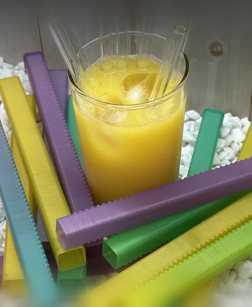
Holder for Reusable Straw

Stellar Blooms

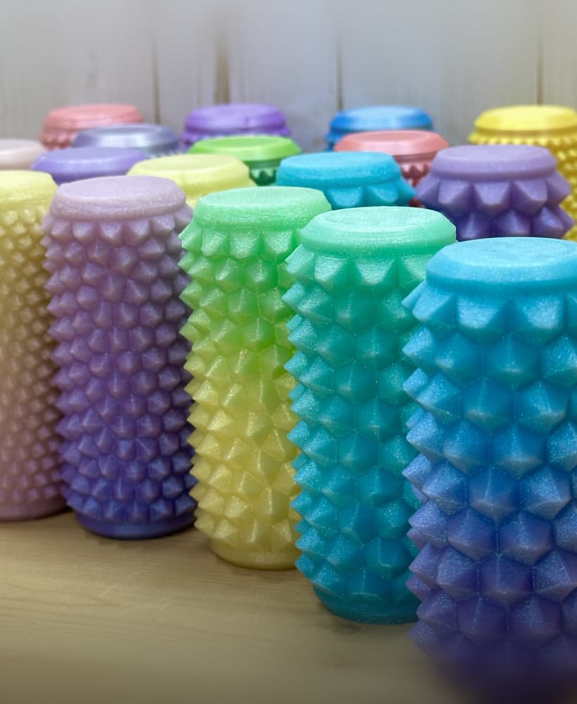
Bump Boxes

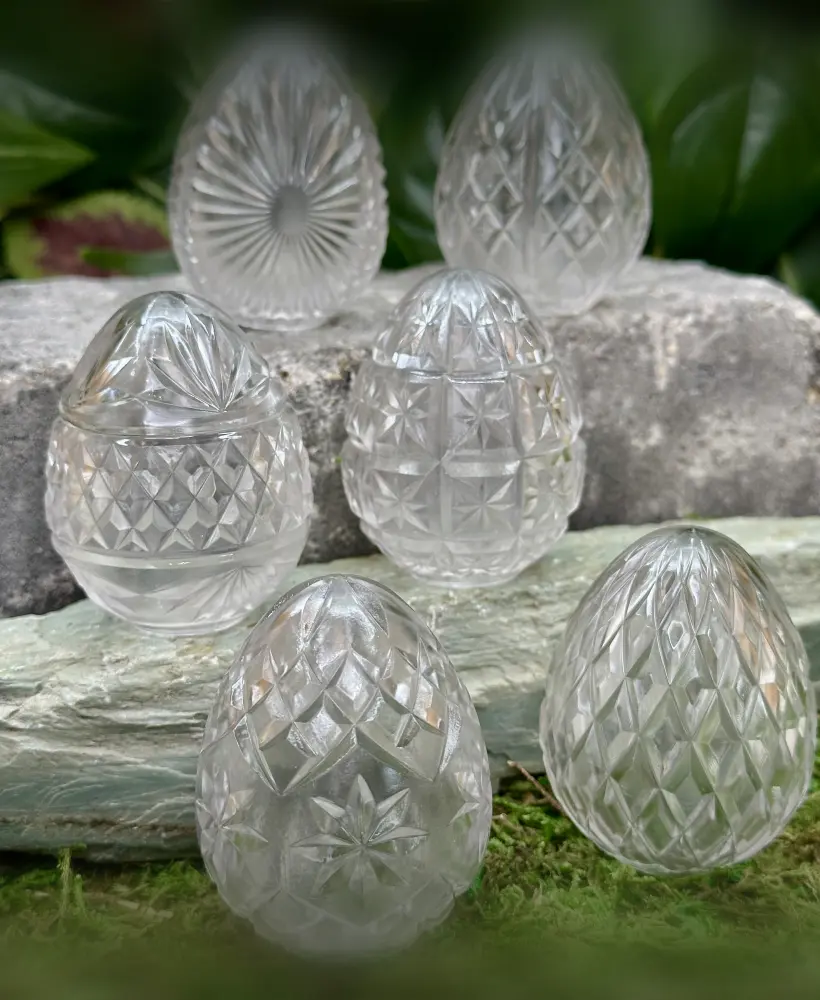
Cut Crystal Eggs - Set 2
Thank you so much for all these medical models. You dont know how much i appreciate them! ❤️
Looking for a fun way to spice up your conversations? This tool lets you send customized messages and notifications that are perfect for pranking your friends. It's simple to use and full of creative features. Check it out and start having fun today!
The dynamic shoulder rotator is a great tool for improving shoulder strength and mobility. It’s especially helpful for athletes or anyone recovering from shoulder injuries, as it targets key muscles to enhance stability and reduce the risk of future issues. Staying active and injury-free is as important for athletes as staying connected is for sports fans, which is why I also love using platforms like Sportzfy to keep up with all the latest sports a
If you're planning a visit to Golden Corral, I highly recommend checking out this page. It has all the updated menu prices and details, which made it so much easier to plan our family dinner. It’s a great resource if you want to know what to expect before you go!
Fascinating model for medical education! The detailed assembly instructions are really helpful. It's amazing how 3D printing is revolutionizing medical training. Speaking of clear instructions, I recently found this handy tool for fixing audio issues on phones - equally user-friendly! For those in the medical field, how do you think models like this compare to traditional learning methods?
When unable to log in to play, it’s often a good idea to ensure your network is stable or verify server status. Meanwhile, take a breather by browsing this site, which lists the full menu of Kyan Cafe. With options ranging from energizing coffee to tasty desserts, it’s the perfect way to relax while troubleshooting.
If your phone speaker isn’t working properly due to water or dust, you might find this helpful website useful. It provides a quick and simple way to restore clear audio by using sound frequencies to dislodge any trapped particles. It’s an easy solution to try before considering professional repairs!