


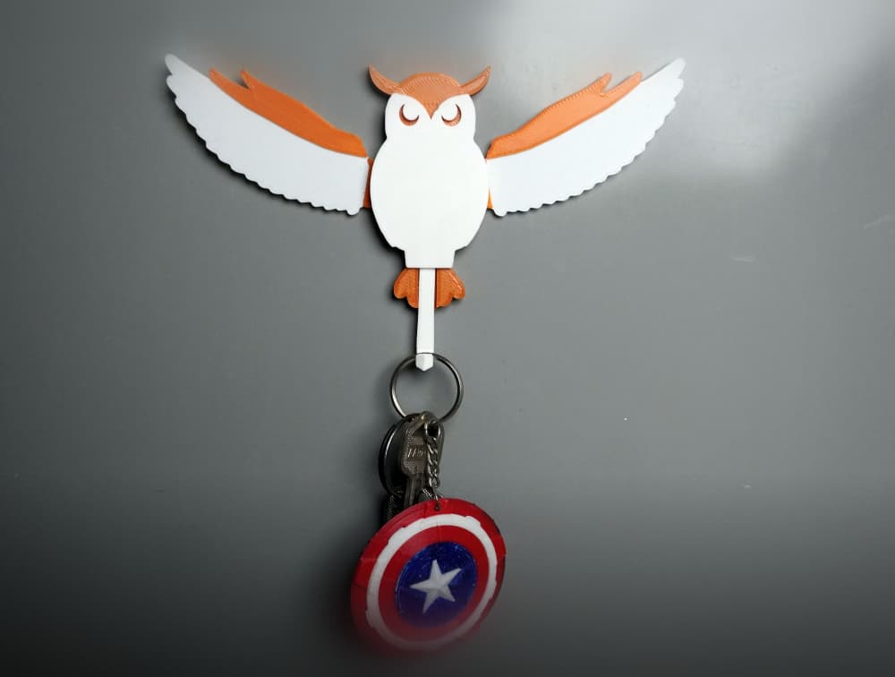
Owl Key Holder with Rising Wings
Description
Okay, this is gonna be a long text since it has several moving parts and needs carefulness to work perfectly. Since most of the users will only care about the if they have the proper materials for the print, I will give requirements first to let you asses the do-ability.
Requirements
a 3D Printer, obviously. 14 x M3 DIN 934 Nuts. 6 x M3x8 DIN 934 Countersunk screws. 2 x M3x12 DIN 934 Countersunk screws. 2 x M3x16 DIN 934 Countersunk screws. 2 x 5mm x 1.5 mm (Neodymium) magnets. A lighter. Something to hold hot screw and nut. An adhesive.Note: You can use 8 M3x8 and 2 M3x12 and fix the loose nuts with adhesive. I have used 2 nuts to lock moving pieces screws to allow them to move. The reason I used 2 nuts to lock screws is to allow repair-ability. By this method, any part can be changed quickly. Several Notes:
The figure has a huge internal volume that remains unused. I have left it for future upgrades. You can easily add springs, etc, in that volume. I used metal screws for the thin parts for endurance, since prototypes broke on the thin connecting rods. The two circles on the internal side of the wings are there to reduce contact area and friction, but to allow movement without jiggling in other directions. It does not work perfectly, but it works fine enough. I do not think there is a solution without increasing the complexity.How to:
In here I will order topics by part. 1st and 3rd files requires a mid-print pause to insert nuts and pause post process script at the slicer. All other operations are after printing is done. Printing and Post Process Body:
At the Slicer:
To insert the nut into the print, you need to pause at the correct layer. In this part, it is the 40th layer (0.2mm layer height) and at 8 mm in height. So, pause print at 8 mm.
This part requires support to print better. There is minimal support, so minimal material is wasted.
Also, you can add a support blocker for the nut volume, or you can remove printed supports at the pause. Both of the options have worked nicely for me.
At the Pause:
I have screwed a screw into nut just enough to hold it but not enough to extend through it. My screw was long so I was able to heat my nut without burning myself. If your screw is short, please use something like a pliers. With a simple lighter, I heated my nut for around 3-5 seconds. After that, I inserted the nut into the place while giving attention to its orientation. It needs to be perpendicular to the print surface. I have eyeballed it, and that was enough. So no levels required.
Post Processing:
Except for taking the supports off, there is no need for post-processing in this part. Wings:
At the Slicer:
In this part, you again need to pause mid-print and insert nuts in the same method. This parts nut tolerances are tighter in the Z axis, but it did not cause any issues in my prints. It is like that so the nut is oriented better, since out of orientation might cause the mechanism to get stuck. In this part, the pause height is 4.5 mm or the 23rd layer on 0.2 mm layer height.
At the Pause:
Same old pushing your heated nuts into the print thing. No other things to do.
Post Processing:
As mentioned before, instead of finicky, thin and breakable connections, I have used screws. Countersunk screw are best in this case since their top is flat and it is a nice surface to balance screw. In the top hole, just put a drop of glue and fix the M3x16 screw. You can use 12mm as well, but you cannot do a double nut in that case. Do not worry about the screw extending beyond the walls of the main body, since the backing plate has holes to allow a little bit more space. Legs:
At the Slicer:
Nothing special. Just slice. No pauses here.
Post Processing:
Paws: The bottom hole is for the magnet. Drop a little glue and fix the magnet. Top hole is for the M3x12 screw. Drop a glue and fix the screw as well. Again, if you don't want to use a double nut, you can use M3x8.
Legs: Nothing to do. Please move forward. Assembly:
I think this is pretty straightforward. Please place the wings into the correct position in the front of the body: the nutted hole to the circular identation, screw to arc opening. Without the screw from the back of the body, wings will seem as unstable, but after you screw in the wing, it holds its place. Of course DO NOT tighten the screw. The best method I found is, screw tight then loosen it a little.
In the leg and the wing connection screw, I preferred to have double nuts locking each other. Simple as that. Then simply screw the backplate and you are done. I have added 2 hangs since 1 will be unstable. Also, I am currently using it with double-sided tape, which works fine.
Photographs:
Photo 1: Inserting nuts into the body. https://media.printables.com//media/prints/1329466/rich_content/03c07970-5b07-42b0-aa0d-c1df568450cd/thumbs/inside/1920x1440/jpeg/img_0222.webp
Photo 2: Inserting nuts into the wings. https://media.printables.com//media/prints/1329466/rich_content/16fcd6d4-e3ae-4266-b0da-f187ccee7106/thumbs/inside/1920x1440/jpeg/img_0226.webp
Photo 3: Body and wings. https://media.printables.com//media/prints/1329466/rich_content/7771f96b-a45e-4e7c-93b2-fa7c07e4b3cb/thumbs/inside/1920x1440/jpeg/img_0229.webp
Photo 4: The wing getting its screw.
https://media.printables.com//media/prints/1329466/rich_content/eee18bf7-7fa6-4d69-98d8-0b29f064d5c5/thumbs/inside/1920x1440/jpeg/img_0232.webp
Photo 5: The wing is placed correctly. https://media.printables.com//media/prints/1329466/rich_content/fbfd2736-9bf3-4f47-aafc-6580de027ede/thumbs/inside/1920x1440/jpeg/img_0231.webp
Photo 6: Backplate, legs, and paws. https://media.printables.com//media/prints/1329466/rich_content/fbfd2736-9bf3-4f47-aafc-6580de027ede/thumbs/inside/1920x1440/jpeg/img_0231.webp
Photo 7: Paws, magnet and screw attached. https://media.printables.com//media/prints/1329466/rich_content/86daa717-5e1a-4067-83fc-66d7b06db307/thumbs/inside/1920x1440/jpeg/img_0234.webp
Photo 8: Whole assembly with backplate off https://media.printables.com//media/prints/1329466/rich_content/4047f941-a808-440f-9c2f-6057719984d1/thumbs/inside/1920x1440/jpeg/img_0235.webp
Photo 9: Backplate on, with double-sided tape. https://media.printables.com//media/prints/1329466/rich_content/6e6ce5d3-2f30-496e-8fde-5d0c4e38d87f/thumbs/inside/1920x1440/jpeg/img_0236.webp
Final note 1: I am really sorry for the innuendos. I could not stop myself.
Final note 2: I have placed my nickname in the internal parts of the model. I hate the visible nicknames in the model. I think it makes them uglier. However, I also love recognition, so I have placed it in internal parts.
Owl Key Holder with Rising Wings
Owl Key Hanger | Functional Key Holder

Owl Catchall Tray – 3D Printed Owl Key Bowl – Woodland Entryway Organizer – Owl Trinket Dish STL

Dracula Skeleton Key – Gothic Bat Wing Key Prop for Vampire Decor

Owl Key Bowl STL – Decorative Entryway Catchall Dish, Rustic Owl Sculpture Organizer, 3D Print Home

Owl Key Holder STL – Valet Bowl & Entryway Organizer
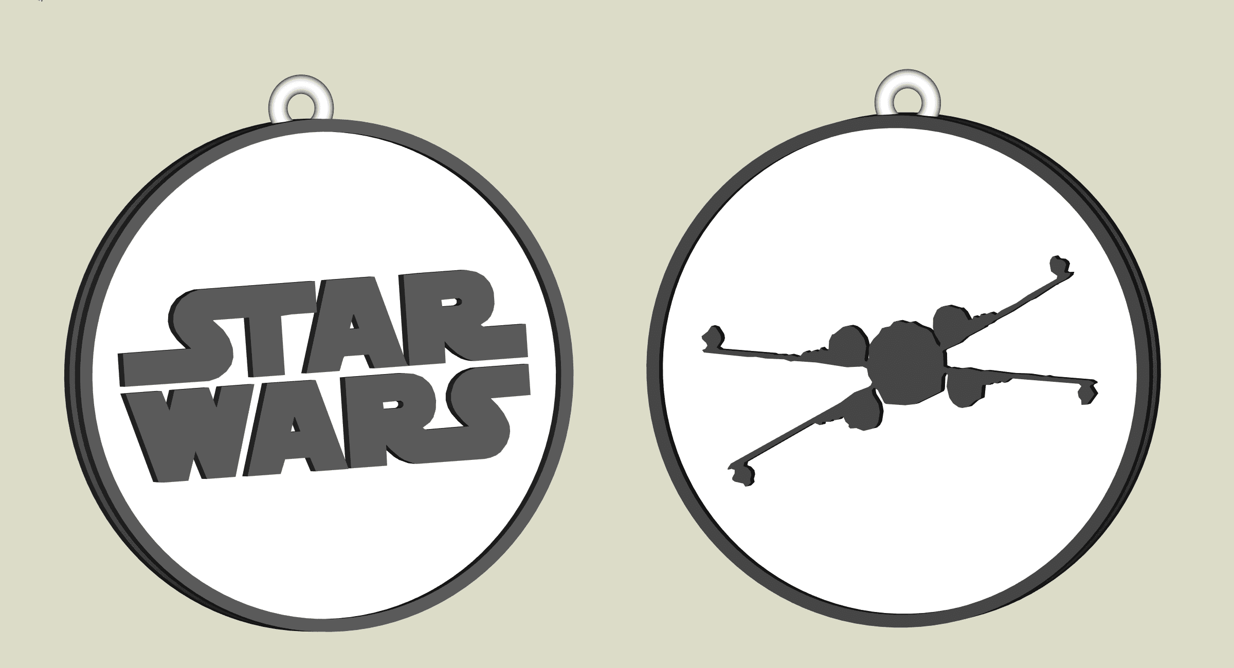
Star Wars X-Wing key chain, earring, dogtag, jewlery

Articulated Owl — Wing-Flapping Wise Friend
.png&w=3840&q=75)
Owl Organizer – 3D Candy Container, Key Holder, Ashtray STL

Sculptural Owl Entryway Catchall Tray | Modern Key Holder Organizer Decor

Angel Wing Catch-All Bowl – Elegant Sculptural Key & Entryway Tray

Geometric Owl on Crescent Moon Catchall – Modern Entryway Key & Mail Organizer

Rise of the Phoenix – Sculptural Vase with Wings and Flame Motif

Flying Owl: Adjustable Book Nook
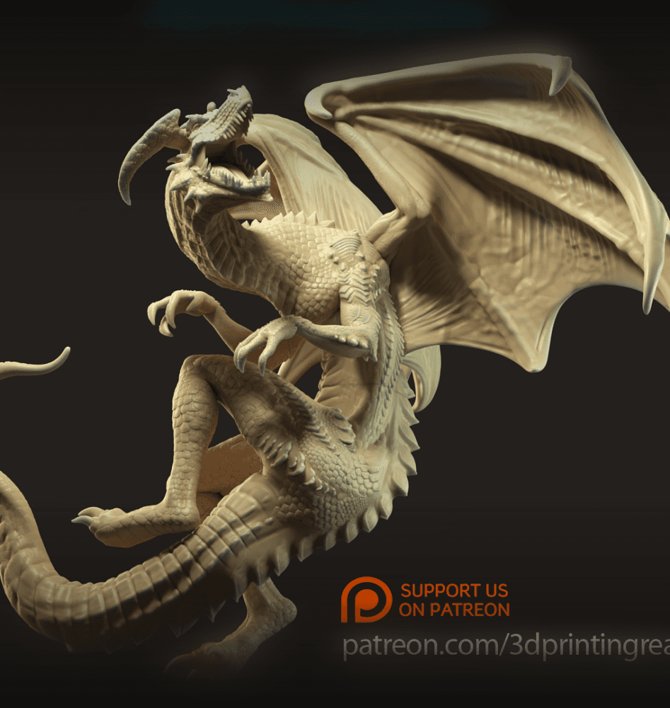
Glaurung the Deceiver
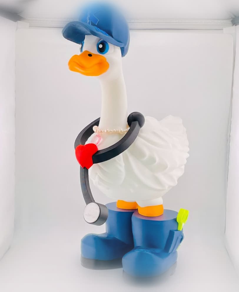
EMS Goose Gear for Porch Goose

Phoenix Book Nook Insert - Bookshelf Decor

Dragon Wall Key Holder

Owl - 5 Layer

Blob Owl - Mini Modular Articulated Art Toy
