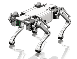


Quadruped I
A quadruped robot with the capability of computer-vision-based tracking and following. This project was created for a university capstone project. The model is based on an existing open-source project (Diy quadruped robot).
**You can support my work and buy me a coffee here: **Buy me a Coffee! It helps a lot and enables me to continue this hobby!
Print InstructionsUse organic supports where it's needed. 15% infill. Use PETG, ASA, ABS or any other more stiff material. The Feet can be printed in any material, but something softer like TPU is nice.
Necessary/Good to have tools needed before starting the project:
Proper wire cutters, wire strippers a precisions screwdriver set are necessary. You will also need a soldering iron to solder wires and to press heat inserts.
Crimping Tool AliExpress Link Amazon Link Hex Key set AliExpress Link Amazon Link Wire cutter AliExpress Link Amazon Link Wire stripper AliExpress Link Amazon Link Precision Screwdriver Set AliExpress Link Amazon Link Heat insert set AliExpress Link Amazon Link Heat insert tip - set AliExpress Link Amazon Link Soldering Iron - Generic (Budget) AliExpress Link Amazon Link Soldering Iron - TS101 (Premium) AliExpress Link Amazon Link General soldering starting kit AliExpress Link Amazon LinkInstallation
To use this code simply download the repository onto the raspberry pi, install the requirements, set up the pi for camera and the servo library usage, and run python3 control-quadruped. This will start the walking motion and print out the pi's IP and port. Run the controller on your computer, setting the IP and port given by the pi and the robot will start taking momentum data from the controller.
- Connect the motors to raspberry pi and run the calibrate command, this will center all of the motors.
- Cut the would to shape and print out the front and side of the body
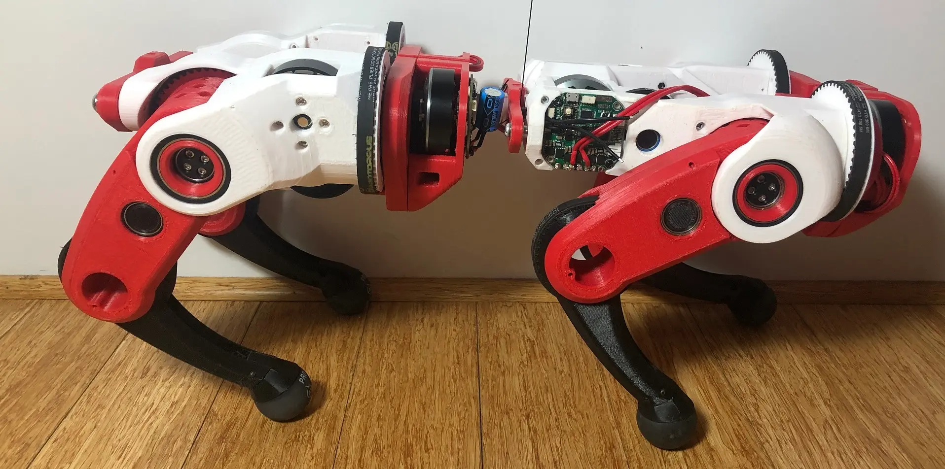
- Install hip motors
- Print the legs
- Set up each leg without mounting to the motors
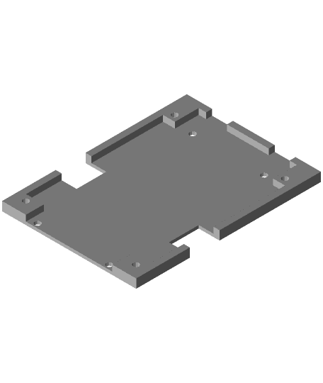
- Continue building from the hip by placing the motor mount plates
- Mount the shoulder and elbow motors, attach the leg (make sure to calibrate before)
- Mount components by screwing them into the wood board. For the electrical
- Add a camera if you want
For the electrical just hook everything to the PWM (https://www.youtube.com/watch?v=9jcEwn7GzNs&ab_channel=MakerTutor) and camera with camera ribbon or USB. For battery power go from battery to a buck to the pi/motors. We struggled with voltage surge and Pi cycling so consider isolating the batteries or using a capacitor to handle the load.
Computer vision controllerThe computer vision controller has a few extra steps that can seen here. Specific to the computer-vision controller you will also need to run python3 image-sender/rpi_send_video.py to pass camera data to you computer, in this case make sure to change the IP and Port to the ones used by the controller.
IntroThis project was created with the intention of developing a robot that can follow users as a proof of concept for a larger assistant quadruped. The associated code allows for keyboard based control or computer-vision-based control and was structured such that new controllers can easily be implemented by sending momentum packets to the raspberry pi.
Robot ControlThe robot uses an inverse kinematic model to determine how to position the foot in the requested location. Some of the math for this can be seen in the model directory with the jupyter notebook
Bill of MaterialDownload the BOM in the download section.

Quadruped II.

Spider Legged Quadruped Planter
full 3d printed BLDC quadruped
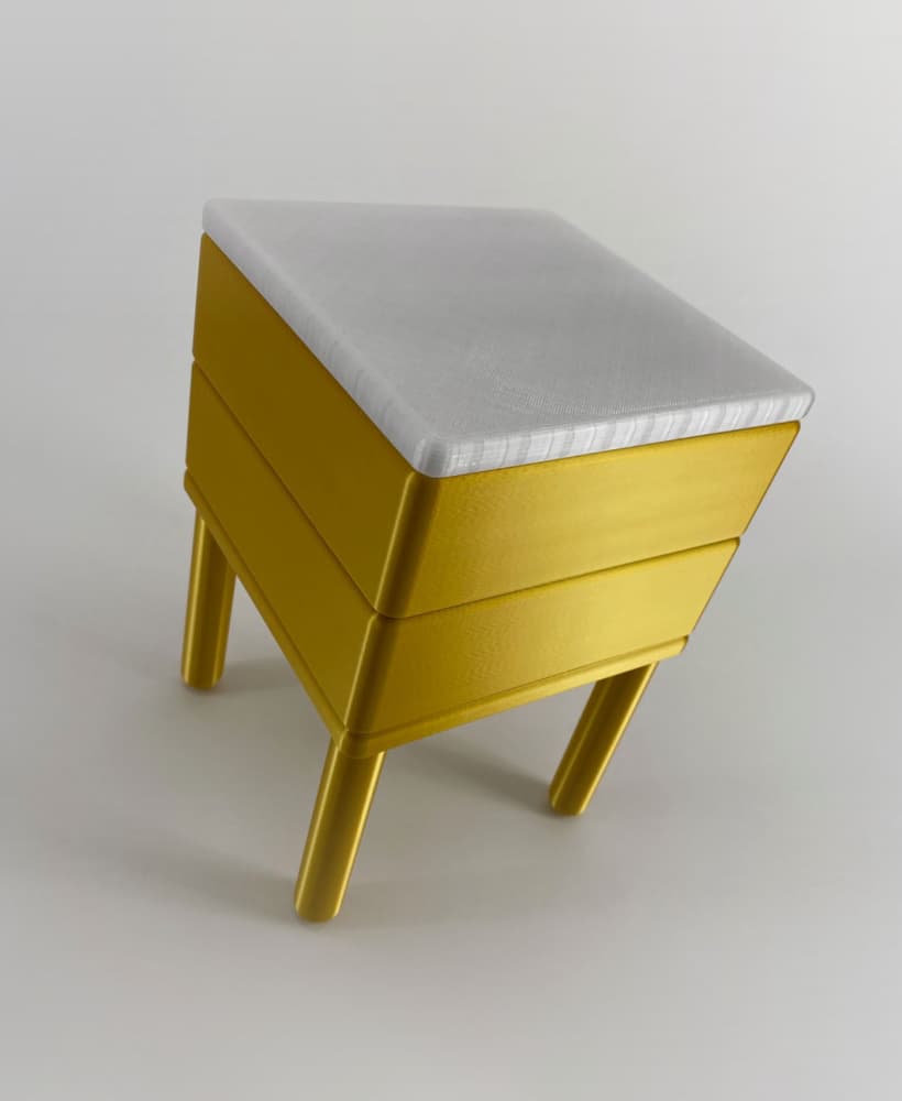
Jewelry Box Tea Box Makeup Organizer Container Bin

Titan - Qudruped
Q1 robot custom parts (with scad)

Wheeliebot

Robotic Arm

Penguin - Hatchling
BLOOM CLIPS | MAGNETIC FLOWER WITH PETAL CLIPS

Skeleton RattleSNEK

Ice Cream Narwhal - Hatchling

Star Cookie Tadling

8x8 MU - MultiBoard Octagon Plate - 4x Ironing Stack

Baby Candy Corn Dragon
Lizard - Hatchling

Crystal Gem Dragon - Hatchling
Pumpkin Squash Hatchling Egg

Alicorn - Hatchling