


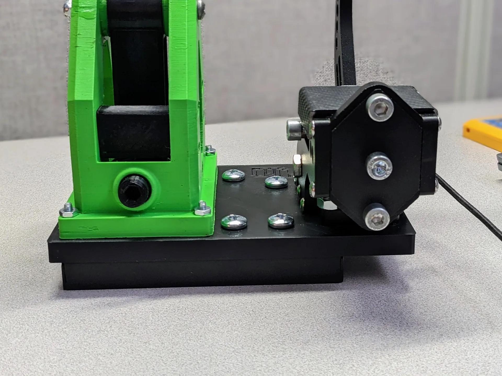
Sim Racing Sequential shifter
Parts list (does not include mounting hardware)
- bike grip
- (m3 x 25)x2 + nuts. For mounting switches only use top holes
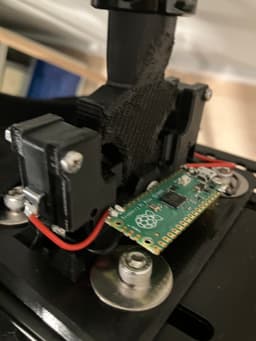
- m5 x 30 + nut. For handle pivot. Raspberry Pi PICO (with Arduino)
- limit switches https://www.amazon.com/12PAack-Action-Button-Microwave-MXRS/dp/B083C113YL/ref=pd_day0fbt_hardlines_thbs_d_sccl_1/131-1981908-9981927?pd_rd_w=7KQDH&content-id=amzn1.sym.06aea998-aa9c-454e-b467-b476407c7977&pf_rd_p=06aea998-aa9c-454e-b467-b476407c7977&pf_rd_r=VDC2ZVMY2T0QMKBCZJT9&pd_rd_wg=zGb5w&pd_rd_r=6db630ea-ac20-4b5d-9421-8de90b51f96b&pd_rd_i=B083C113YL&th=1
code below will work for buttons soldered to GPIO 1,2,3,4,5,6,7,8,9 and for a joystick on GPIO 27 and 28 if you want to repurpose it or add more functions.
#include <PicoGamepad.h>
PicoGamepad gamepad;
// 16 bit integer for holding input values int xVal; int yVal;
void setup() {
Serial.begin(115200);
pinMode(LED_BUILTIN, OUTPUT);
// X Potentiometer on pin 27 pinMode(27, INPUT); // Y Potentiometer on pin 28 pinMode(28, INPUT);
// Buttons on GPIO 0, 1, 2, 3, 4, 5, 6, 7, 8, and 9 pinMode(0, INPUT_PULLUP); pinMode(1, INPUT_PULLUP); pinMode(2, INPUT_PULLUP); pinMode(3, INPUT_PULLUP); pinMode(4, INPUT_PULLUP); pinMode(5, INPUT_PULLUP); pinMode(6, INPUT_PULLUP); // Add GPIO 6 as input with internal pull-up resistor pinMode(7, INPUT_PULLUP); // Add GPIO 7 as input with internal pull-up resistor pinMode(8, INPUT_PULLUP); // Add GPIO 8 as input with internal pull-up resistor pinMode(9, INPUT_PULLUP); // Add GPIO 9 as input with internal pull-up resistor }
void loop() {
// Get input value from Pico analog pin for X axis xVal = analogRead(27); // Map analog 0-1023 value from pin to max HID range -32767 - 32767 xVal = map(xVal, 0, 1023, -32767, 32767); // Send value to HID object gamepad.SetX(xVal);
// Repeat with Y pin for Y axis yVal = analogRead(28); yVal = map(yVal, 0, 1023, -32767, 32767); gamepad.SetY(yVal);
// Set buttons: 0 = GPIO 0, 1 = GPIO 1, 2 = GPIO 2, 3 = GPIO 3, 4 = GPIO 4, 5 = GPIO 5 // 6 = GPIO 6, 7 = GPIO 7, 8 = GPIO 8, 9 = GPIO 9 gamepad.SetButton(0, !digitalRead(0)); gamepad.SetButton(1, !digitalRead(1)); gamepad.SetButton(2, !digitalRead(2)); gamepad.SetButton(3, !digitalRead(3)); gamepad.SetButton(4, !digitalRead(4)); gamepad.SetButton(5, !digitalRead(5)); gamepad.SetButton(6, !digitalRead(6)); // Set button 6 based on GPIO 6 state gamepad.SetButton(7, !digitalRead(7)); // Set button 7 based on GPIO 7 state gamepad.SetButton(8, !digitalRead(8)); // Set button 8 based on GPIO 8 state gamepad.SetButton(9, !digitalRead(9)); // Set button 9 based on GPIO 9 state
// Send all inputs via HID gamepad.send_update();
// Flash the LED just for fun digitalWrite(LED_BUILTIN, !digitalRead(LED_BUILTIN)); delay(100); }
Sim Racing Sequential shifter
GT Omega Cockpit Sim Racing Rig Adapter For Beavis Racing Shifter and Handbrake

Logitech Z906 Sim Racing Cockpit Mounts V2

AlphaWindSim - Sim Racing Wind Simulator

Sim Racing Power Supply Holder

Cup and Phone Holder mount for sim racing cockpits

Sim Racing Heel Rest
Sim Racing E-brake from USB keyboard
Logitech Shifter Stabilizer

TH8A Shifter Clamp

PORSCHE GT3RS 992 Wall Tachometer Clock
Meta Quest 3 Adjustable Strap
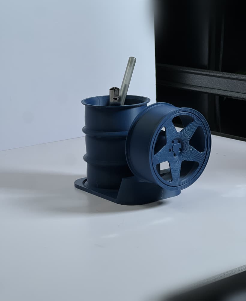
FREE KnP Inspired Wheel Pen Holder

Hellcat Wheel Headset and Controller Stand

GT3 RS Wheel Controller and Headset Stand

TE37 V2 Simple Wheel Controller Stand

Tire Controller Stand

TE37v2 Wheel Controller and Headset Stand
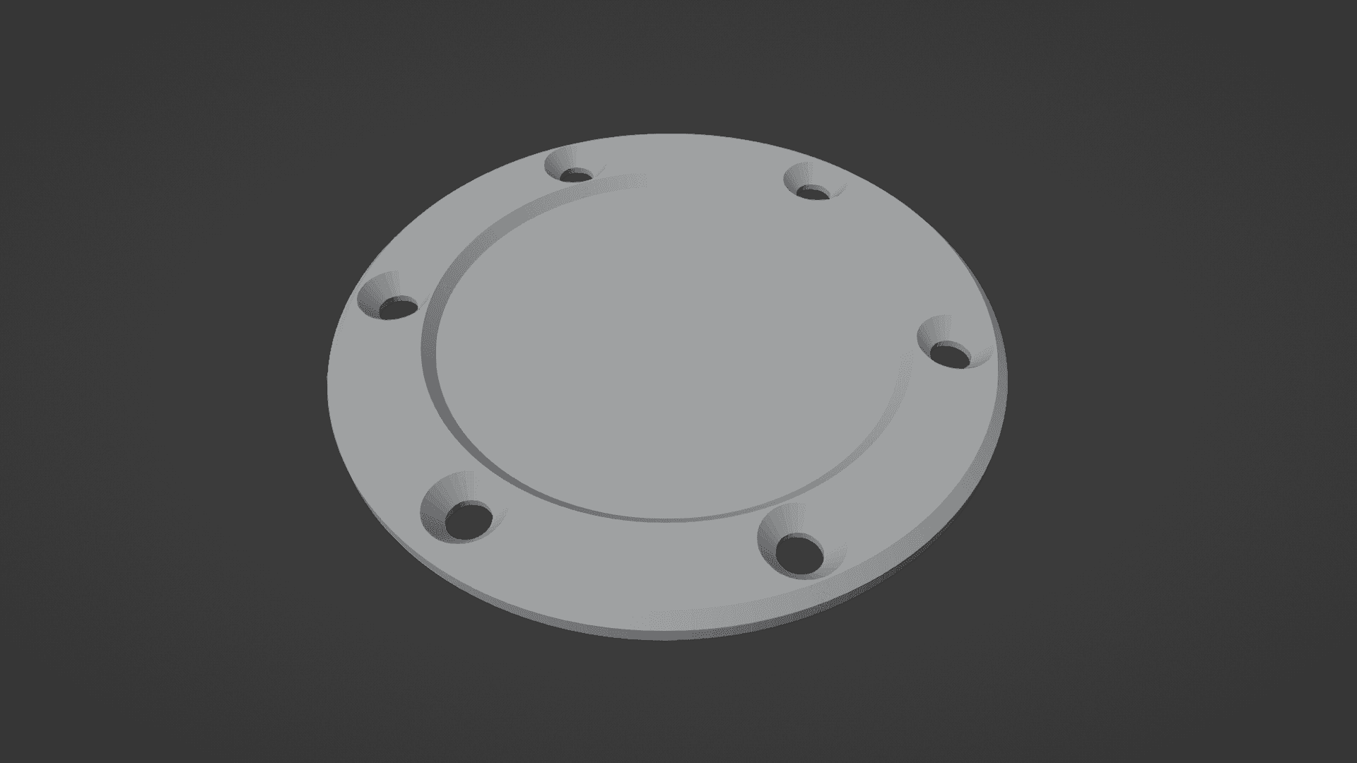
Steering wheel center cap

TE37 Wheel Desktop Clock w/ Stand
