


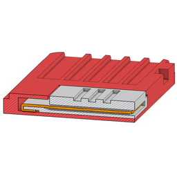


Nintendo Switch Game Card / Cartridge RCM Jig
This is an RCM jig for a Nintendo Switch which includes a holder that fits in the Game Card slot.
This is technically a remix of an off-site design by Joe_84156 on Printables which is CC BY-NC-SA and allows remixes like this. I have made several improvements to both the game card and jig portion.
Card v2 Notes: I re-made the game card holder in OnShape, and added more tolerance to allow for this method of installing the wires. Additionally, I re-dimensioned the contact slots to be more accurate based on my measurements of a real game card.
Jig v5 Notes: I added notches to keep the wires straight.
Jig v4 Notes: I added slots on the back to help the wires sit flush with the jig.
Jig v3 Notes: I changed the grip used to get the jig out with your finger from a slippery cone to grippy ridges.
Jig v2 Notes: I re-made the jig in OnShape to use a different method of installing the wires that I have found to be much more reliable.
Explanation: By wrapping the wires all the way around the connector edge and leaving some length on the back, you are ensuring two things:
- That contact will be made with the pins reliably, and
- That the wires won't bunch up and ruin your jig, or worse, your Switch.
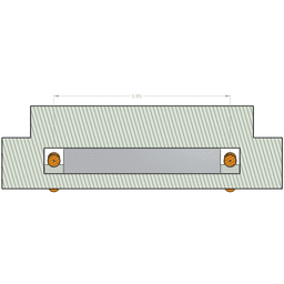
Technical Notes: Joy Con Rail Pin Pitch / RCM Jig Pin Spacing: I wanted to make certain I was using the exact correct dimensions for the RCM jig, so I did some sleuthing and found there were no references to the actual pin pitch of the joy-con rail pins that connect the rail to the Switch itself. I used the fact that people use microUSB cables to make RCM jigs to determine that:
The pin pitch of the connector that connects the joy-con rail to the Switch console is 0.65mm. There are 10 pins, therefore if you want to connect the first and last pin for RCM mode, you must make a jig with exactly 5.85mm spacing between the centers of the pins.
Of course, you can go a bit higher without damaging the Switch, but it is recommended to aim for 5.85 mm. Any smaller can damage the Switch, so if you're making your own and need to err on one side or the other, go wider.
Post-Printing:
- Install the Wire
- Strip some long, thin (about 26 AWG), solid-core wire and install it into the holes with a loop tucked into the notch on the jig's back end. Ensure it's long enough to hang over the edge by at least 3mm on each side.
- Cut the Wire
- Trim the wires so they are even and only 2-3 mm is left hanging off the connector edge.
- Bend and Flatten the Wires
- Bend the wires around the edge of the connector, and push the ends into the shallow slots in the back.
- You want the wires to be flush with the back of the connector. If needed, squeeze the wires with needle nose pliers to fold them around the edge more tightly and push them deeper into the plastic slots. Be careful not to squeeze so hard that you crush the plastic or damage the wires.
- Ensure the wires are straight and flat, and you're done!


Nintendo Switch Game Card / Cartridge RCM Jig

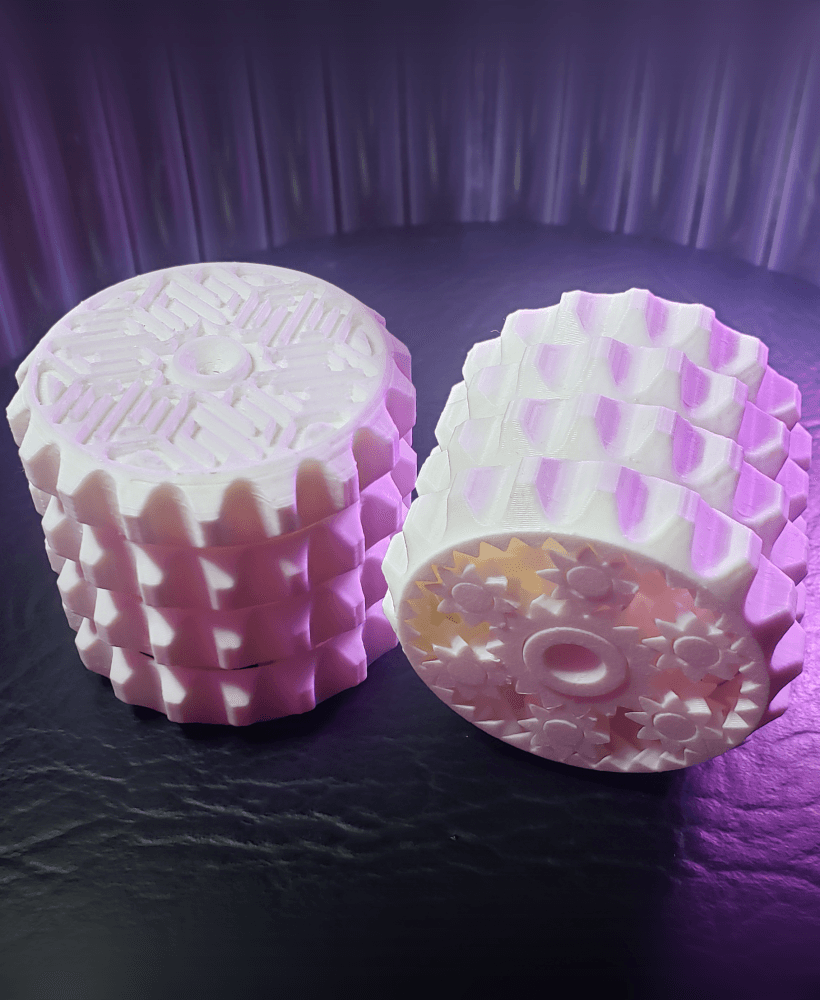
Planetary Gear Benchmark and Demo
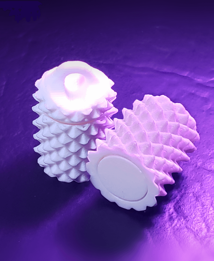
SpikeRoll Micro - Tactile Spinning Layered Fidget Toy
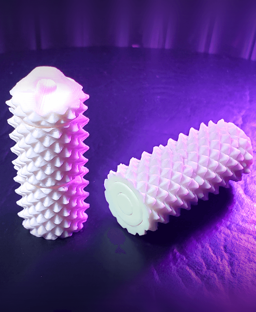
SpikeRoll Mini - Tactile Spinning Layered Fidget Toy

SpikeRoll - Tactile Spinning Layered Fidget Toy
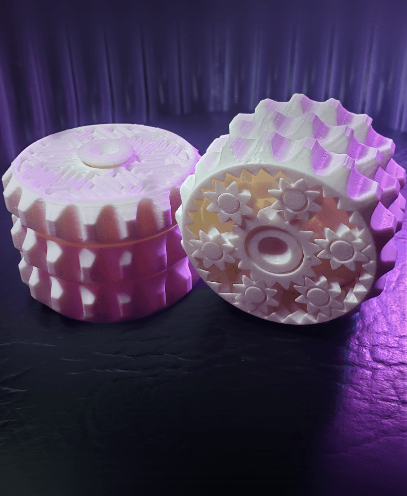
OrbitStack - Tactile Planetary Gear Spinning Layered Fidget Stim Toy

OrbitStack Knob - Tactile Planetary Gear Spinning Layered Fidget Stim Toy
OrbitStack XL - Tactile Planetary Gear Spinning Layered Fidget Stim Toy

Paper Creasing Tools (Pick, MiniPick, Domino)

Cthulhu Statuette (with Mysterious Writings Added)
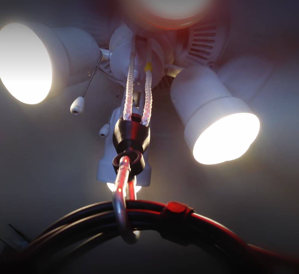
Ball-Socket Swivel Rope Hanger (Ceiling Fan VR Cable Management)

Infest The Rats' Nest Skull (Official KGatLW 3D Model)

Nintendo Switch Cartridge but it is a cartridge holder
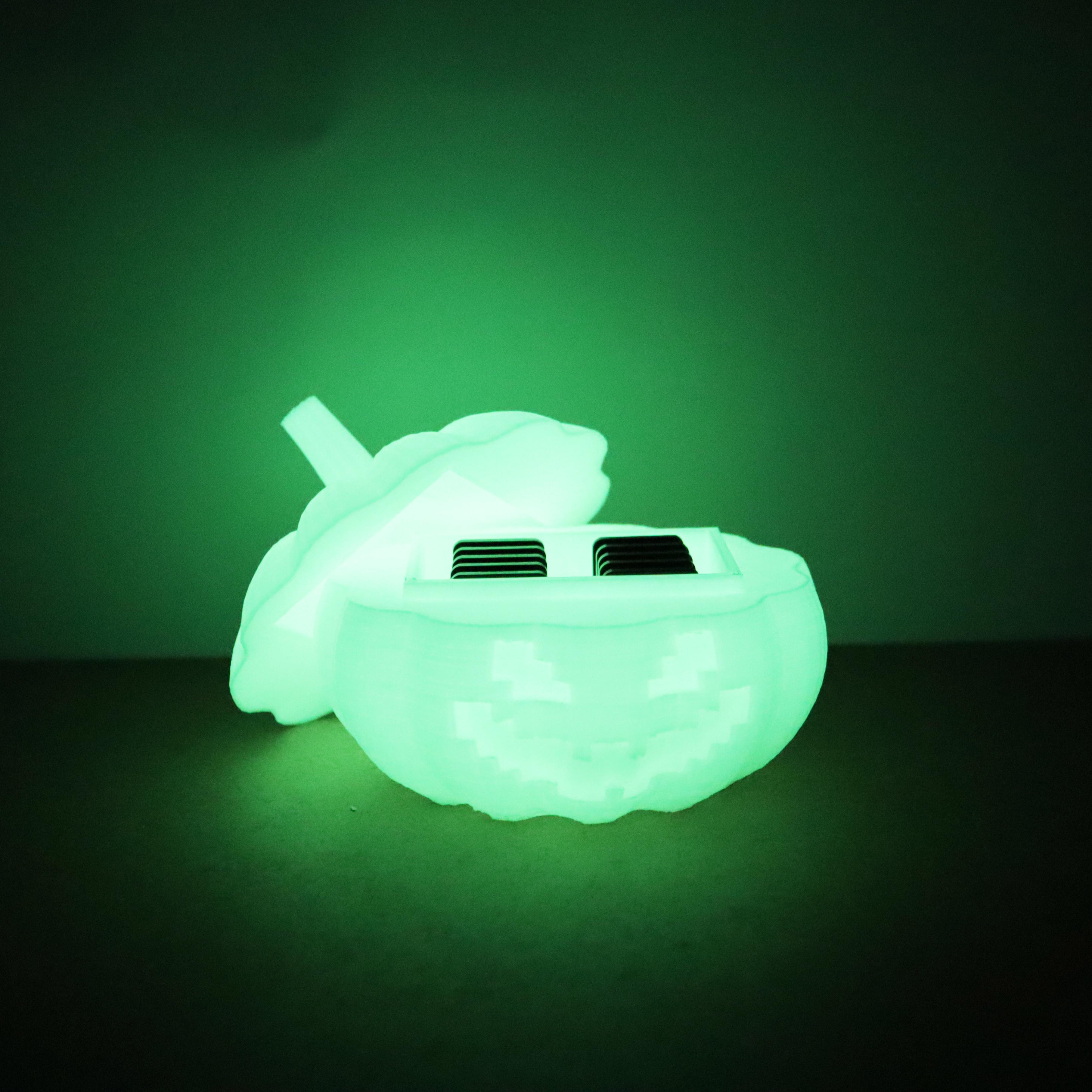
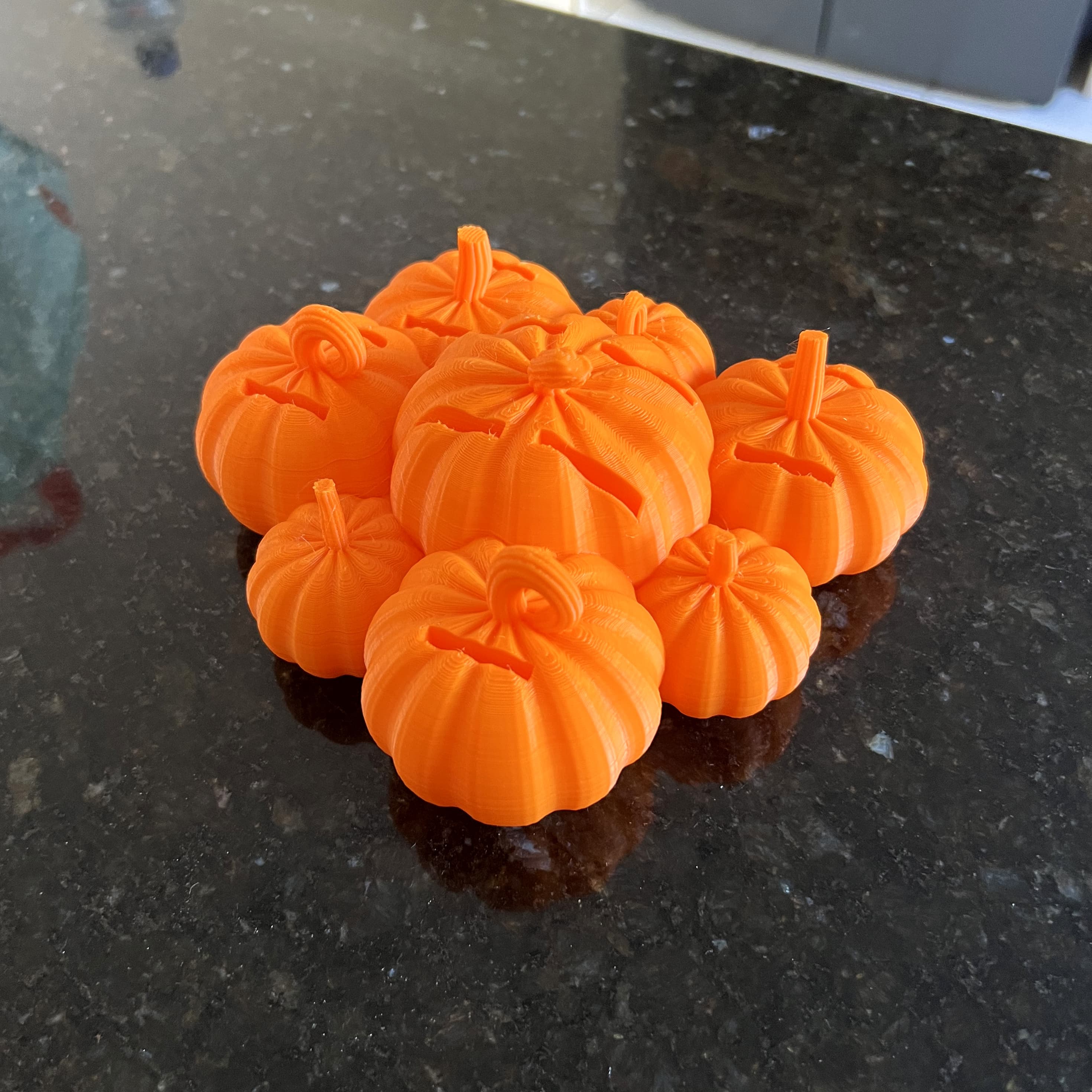
Pumpkin Nintendo switch cartridge box
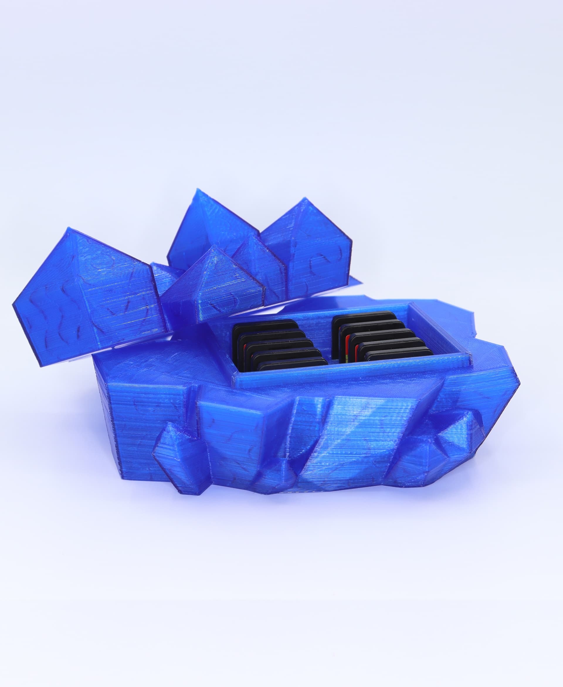
Nintendo switch crystal cartridge box
Pumpkin patch Nintendo switch cartridge holder
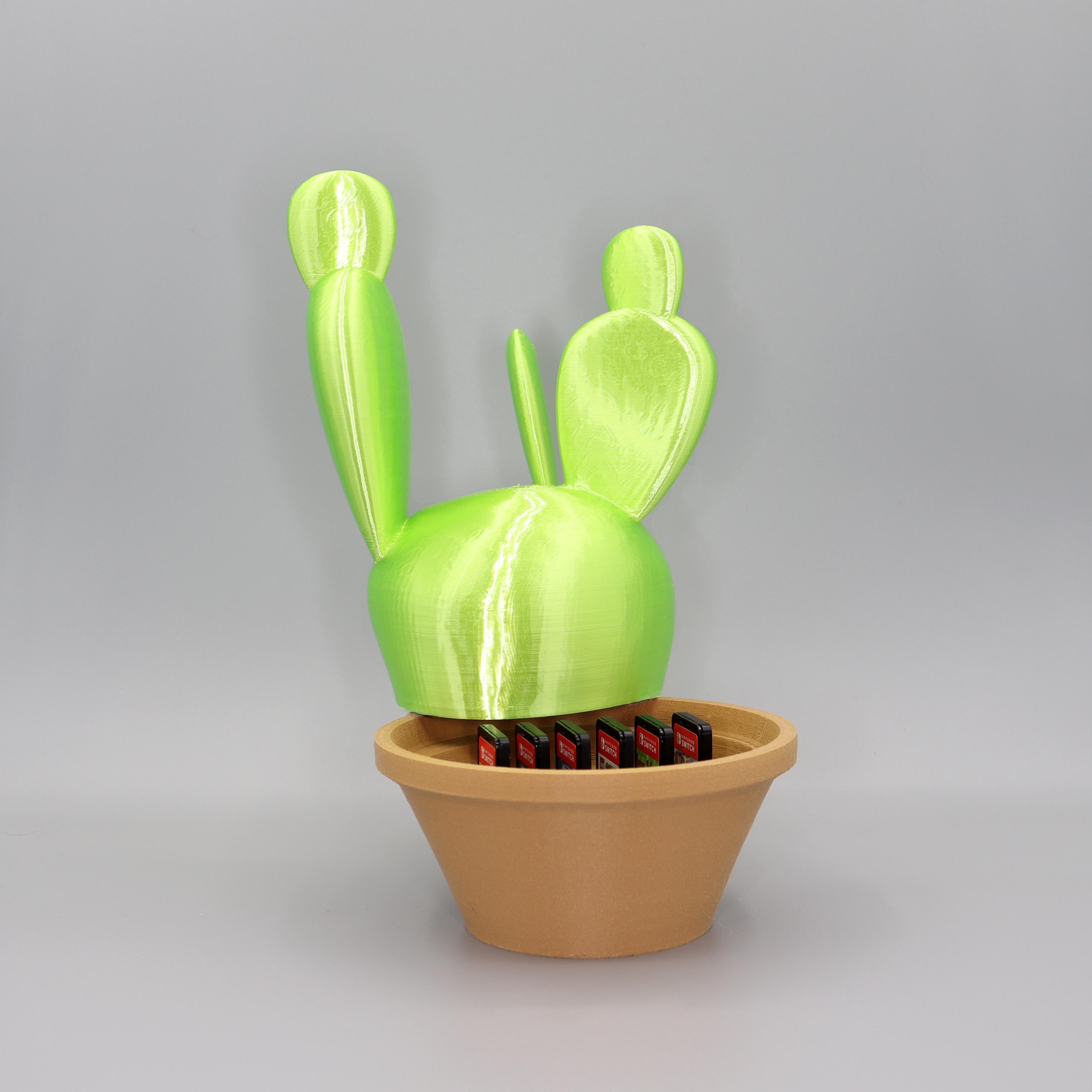
Cactus Nintendo switch cartridge holder

Nintendo Switch Cartridge Organizer for SKÅDIS
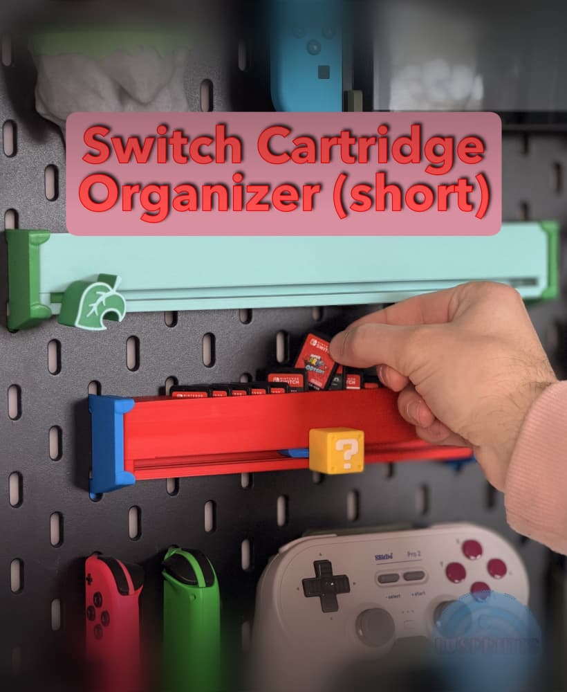
Nintendo Switch Cartridge Slider - Short (12 slots)

Nintendo Switch NES Cartridge Holder v3.5.stl
