Model originally uploaded to Thingiverse at https://www.thingiverse.com/thing:5242102.
Playing with a concept of a self-deploying auto bed level probe after watching DPT's video. Let's get down to the micron!
This one uses a Omron EE-SY310 reflective optical switch (instead of the usual transmissive type) with integrated, temperature compensated Schmitt trigger circuit.
Very similar to Ertsen's design but I wanted the magnet to do double duty and act as the spring, too.
See also the Touch Mi probe and Michael's video for electrical installation and software.
Design is fully customizable, but requires some tuning to balance the magnetic forces and offset height.
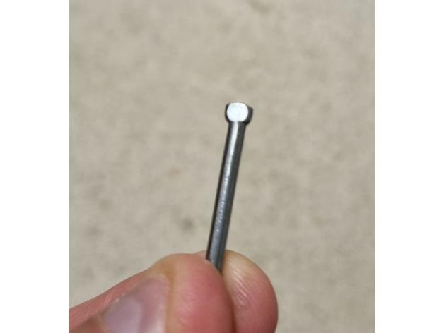
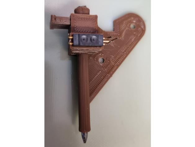
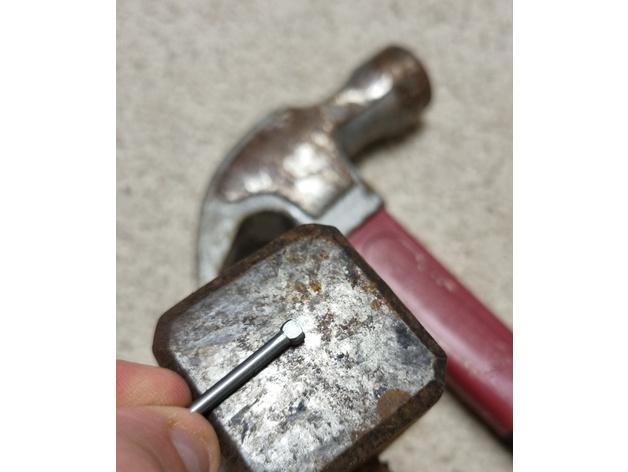
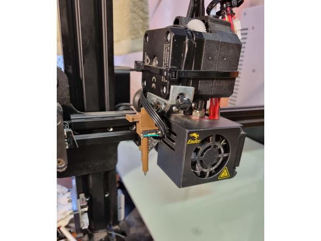
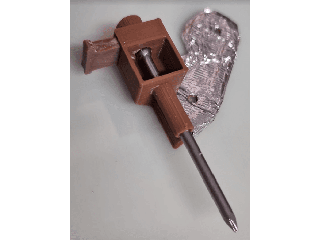
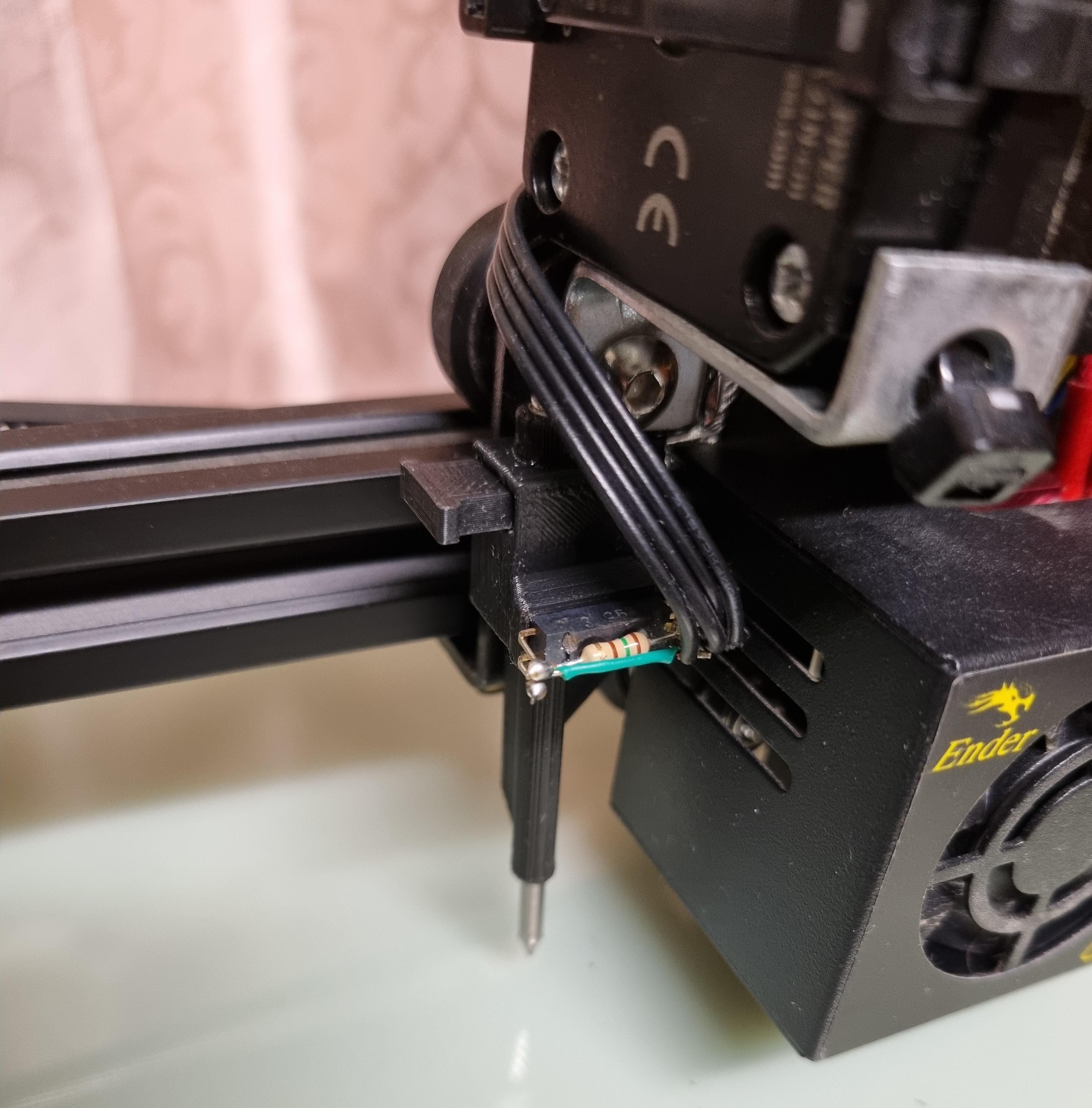
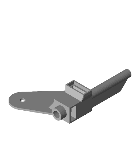
Shown on an Ender 3 using 50mm bullet head nail (2.8mm diameter, I think - it slides in a 3mm drilled out hole). I also tapped the top hole with an M5 thread and made a makeshift iron grub screw by cutting a bolt. Magnet is 6mm diameter x 2.5mm cylinder. Head of nail dipped in white acrylic paint for reflection (shiny convex surface was not detected). Alternatively, hammer or grind the head flat for the anti-rotation version (does not require paint).
From the stowed position, the nail sits above the nozzle height. On X-home motion, the magnet is pushed sideways by the end-stop, dropping the nail probe below nozzle height. In this position there is a little travel which can be detected by an optical sensor. Once the bed has been measured, dropping the nozzle to print height will bring the nail back in range of the magnet and retract it to the stowed position.
The M5 iron grub screw attracts the magnet back to center and also helps extend and strengthen the field.
Not sure how it will handle radiated heat from the hot-end so I wrapped it in aluminium foil under the shroud. Maybe a high temperature filament would be a good idea.
Electrical considerations It seems both the light emitter brightness and detector sensor are influenced by temperature, “the temperature compensation of any Photomicrosensor is difficult”. In this arrangement, the reflective surface moves into the detection zone slowly until enough reflected light reaches the detector. For precision of <0.1mm this means we are operating in the analog detection range (active region) and such temperature dependence of the Schmitt trigger circuit will be significant.
Omron is the only manufacturer of photointerrupters I have come across which specifically mentions this phenomenon and incorporates temperature compensation circuits in some of their products with built-in logic level Schmitt trigger circuits (or at least mentions them as a product feature). Little data is available on measurement repeatability across temperature ranges, however.
UPDATE: All wired up with resistor (150ohm, a little lower than the 190ohm target for 20mA for thermal dissipation, see datasheet) and shunt feeding the LED. I found a long 4-wire stepper cable which already had JST connectors that I was able to re-patch into the mainboard connections neatly. Wired in series with the existing NC end-stop by replacing the ground side wire. Output pin to end-stop, Ground to mainboard and Vcc to ICSP header. The 4'th wire is spare, in case I want to strobe the LED brightly from a separate supply.
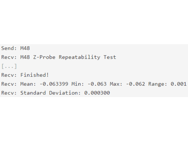
Results: First light! (after a little detour upgrading firmware - don't trust the included bootloader!)
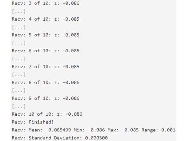
Send: M48 Recv: M48 Z-Probe Repeatability Test [...] Recv: Finished! Recv: Mean: -0.017400 Min: -0.019 Max: -0.015 Range: 0.004 Recv: Standard Deviation: 0.000917
Best result so far is 0.001 range and 0.0003 standard deviation, and worst has been 10x that (with rotation of the nail). We're talking on par with the resolution of the Z measurement, 9 out of 10 samples identical. The anti-rotation version helps a lot with repeatability by constraining the nail to 1dF. The flattened reflective surface does not require painting and we can grind it to a sharp top edge.
Slicer Tricks (Cura) Nice bridging is achieved between thin walls (without explicitly enabling bridging) by setting wall line count to 1. Most lines are only 2x0.4mm lines thick by design. This will leave some structural bulk a little thin so add a Support Blocker covering the whole model, switch to Per Model Settings, Modify settings for overlaps, Infill mesh only, Wall Line Count 1 or more to thicken them back up.